
| Tweet |

Custom Search
|
|

|
||
 TM 9-8000
CHAPTER 7
EXHAUSTAND EMISSION CONTROL SYSTEMS
Section I. EXHAUST SYSTEM
reaches operating temperature. This valve, whose
purpose Is described in paragraph 4-5, is a flat metal
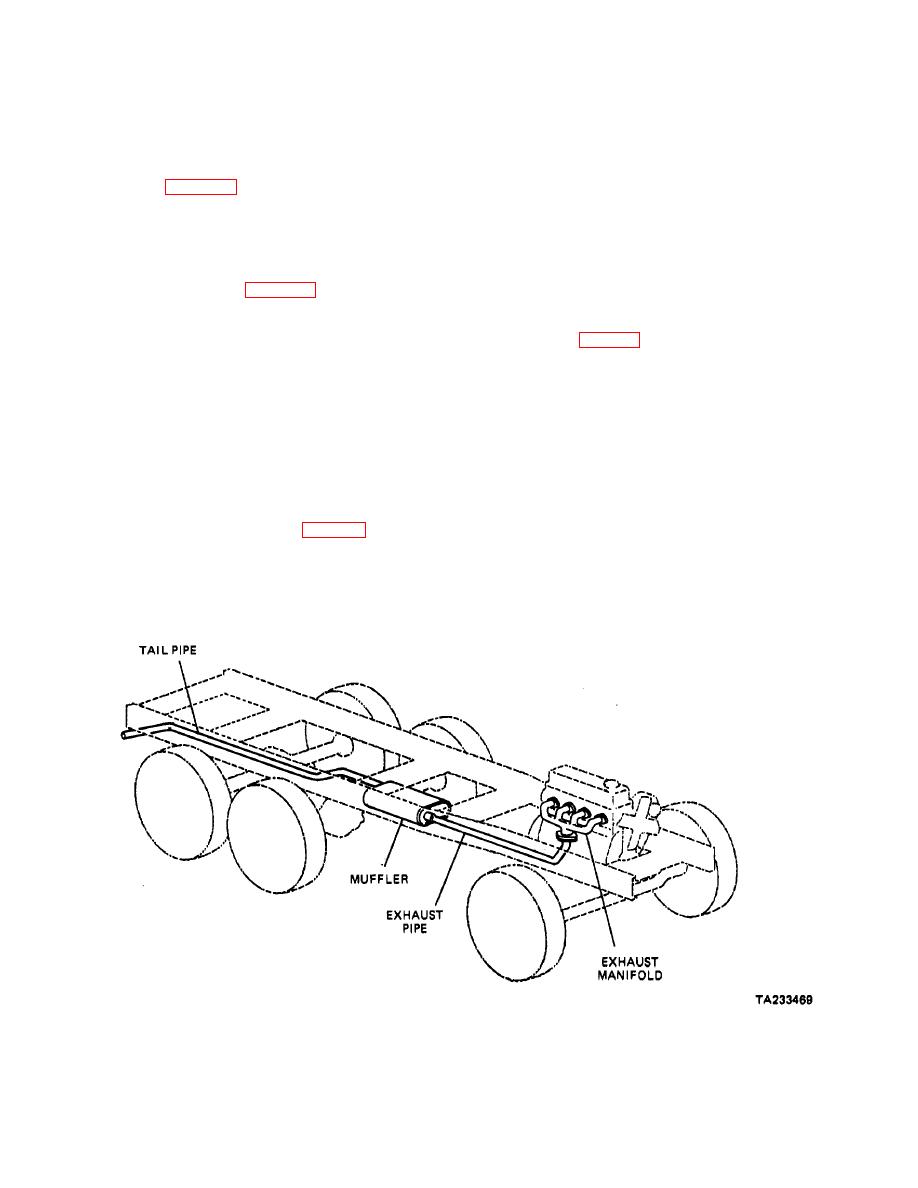
combustion are carried from the engine to the rear of the
plate that is the same shape as the opening that it
vehicle by the exhaust system, where they are expelled
controls. It pivots on a shaft and is operated by a
to the atmosphere. The exhaust system also serves to
thermostatic coil spring. The spring pulls the valve
dampen engine noise.
closed against a counterweight before warmup. The
spring expands as the engine warms up and the
7-2. Exhaust Manifold (Fig. 7-2). The exhaust
counterweight pulls the valve open:
manifold connects all of the engine cylinders to the
exhaust system. It usually Is made of cast Iron. If the
7-4. Muffler (Fig. 7-4).
exhaust manifold Is formed properly, It can create a
a. The muffler reduces the acoustic pressure of
scavenging action that will cause all of the cylinders to
exhaust gases to discharge them to the atmosphere with
help each other get rid of exhaust gases. Back pressure
a minimum of noise. The muffler usually is located at a
(the force that the pistons must exert to push out the
point about midway in the vehicle with the exhaust pipe
exhaust gases) can be reduced by making the manifold
between it and the exhaust manifold and the tailpipe
with smooth walls and without sharp bends. All of these
leading from it to the rear of the vehicle.
factors are taken into consideration when the exhaust
manifold is designed and the best possible manifold is
b. The inlet and the outlet of the muffler usually are
manufactured to fit into the confines of the engine
slightly larger than their connecting pipes so that It may
compartment.
hook up by slipping over them. The muffler then Is
secured to the exhaust pipe and the tailpipe by clamps.
7-3. Manifold Heat Control Valve (Fig. 7-3). A valve
Is placed In the exhaust manifold on some gasoline
engines to deflect exhaust gases toward a hot spot In the
Intake manifold until the engine
Figure 7-1. Typical Exhaust System.
7-1
|
||
|
||


