
| Tweet |

Custom Search
|
|

|
||
 TM 9-8000
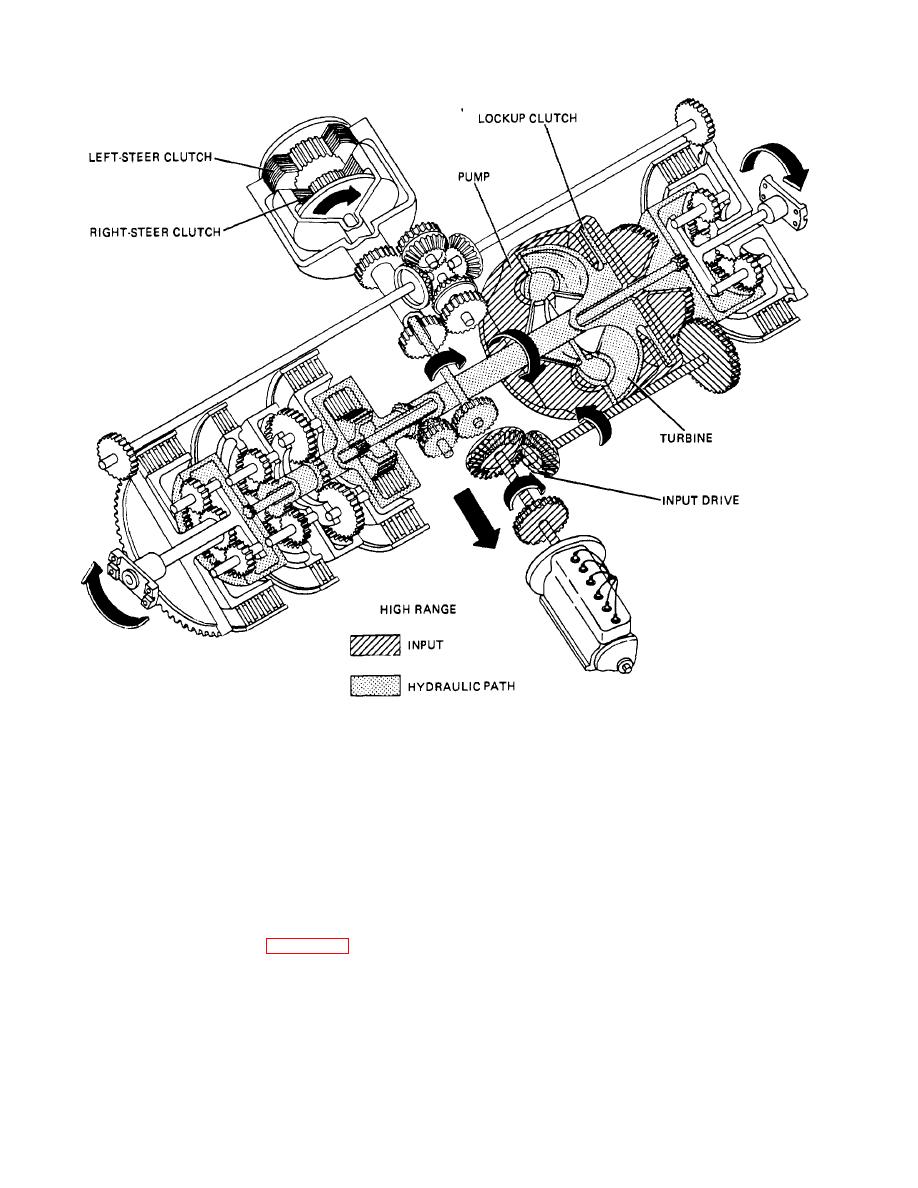
Figure 24.5 Power Flow through Cross-Drive Transmission in High Range. (Part A)
Is being transmitted to the output ring gears. When the
output ring gears remain stationary and the two sun
left steering valve Is actuated by the driver for left steer,
gears cause the planet pinions to rotate and move
oil pressure Is Introduced Into the left-steer-clutch piston,
around the ring gears, thereby rotating the planet
causing the left- steer clutch to engage. The clutch
carriers. The right planet carrier rotates In a forward
receives pressure proportional to the amount of steer
direction and the left planet carrier rotates In the reverse
applied, so that any variation from light to hard left
direction, as shown. This causes the right output flange
steering will result. With the left-steer clutch engaged,
to rotate In a forward direction and the left output flange
the drive Is from the turbine output shaft, through the left-
to rotate Inthe reverse direction. Under the conditions de-
steer clutch to the rear differential bevel gear. This bevel
scribed, which produce left steering, the vehicle pivots to
gear then drives the two engaged bevel gears in
the left.
opposite directions, as shown In figure 24-7. These
driven bevel gears, therefore, drive the two output sun
c. Right Steer In Neutral Range. For right steer In
gears In opposite directions. The output ring gears
neutral range, the low-, high-, and reverse-range
cannot turn In opposite directions because they are both
clutches are disengaged and no driving power Is being
splined to the cross-drive shaft. The
transmitted to the output ring gears. These are the same
conditions as TA233728
24-7
|
||
|
||


