| Tweet |

Custom Search
|
|

|
||
 AIR INLET AND EXHAUST SYSTEM
TESTING AND ADJUSTING
CRANKSHAFT POSITIONS FOR FUEL TIMING AND VALVE CLEARANCE SETTING
STANDARD ROTATION (COUNTERCLOCKWISE)
as Viewed From Flywheel End
ENGINE
CORRECT STROKE
CYLINDERS TO CHECK/ADJUST
FOR NO. PISTON
AT TOP CENTER
VALVES
INJECTORS
POSITION*
INTAKE
3508
COMPRESSION
1-2-6-8
1-2-3-7
3-4-5-7
EXHAUST
3-5-4-7
4-5-6-8
1-2-6-8
3512
COMPRESSION
1-3-6-7-10-12
1-4-5-6-9-12
2-4-5-8-9-11
EXHAUST
2-4-5-8-9-11
2-3-7-8-10-11
1-3-6-7-10-12
3516
COMPRESSION
1-2-5-7-8-12-13-14
1-2-3-4-5-6-8-9
3-4-6-9-10-11-15-16
EXHAUST
3-4-6-9-10-11-15-16
7-10-11-12-13-14-15-16
1-2-5-7-8-12-13-14
REVERSE ROTATION (CLOCKWISE)
- as Viewed From Flywheel End
ENGINE
CORRECT STROKE
CYLINDERS TO CHECK/ADJUST
FOR NO.1 PISTON
AT TOP CENTER
VALVES
INJECTORS
POSITION*
INTAKE
3508
COMPRESSION
1-3-4-8
1-2-7-8
2-5-6-7
EXHAUST
2-5-6-7
3-4-5-6
1-3-4-8
3512
COMPRESSION
1-3-4-6-7-12
1-4-5-8-9-12
2-5-8-9-10-11
EXHAUST
2-5-8-9-10-11
2-3-6-7-10-11
1-3-4-6-7-12
3516
COMPRESSION
1-2-5-6-7-8-13-14
1-2-3-4-5-6-9-10
3-4-9-10-11-12-15-16
EXHAUST
3-4-9-10-11-12-15-16
7-8-11-12-13-14-15-16
1-2-5-6-7-8-13-14
*Put No. 1 piston at top center (TC) position and make identification for the correct stroke. Make reference to FINDING
TOP CENTER POSITION FOR NO. 1 PISTON. After top center position for a particular stroke is found and adjustments
are made for the correct cylinders, re- move the timing bolt and turn the flywheel 360 in the direction of normal engine
rotation. This will put No. 1 piston at top center (TC) position on the other stroke. Install the timing bolt in the flywheel and
complete the adjustments of the cylinders that remain.
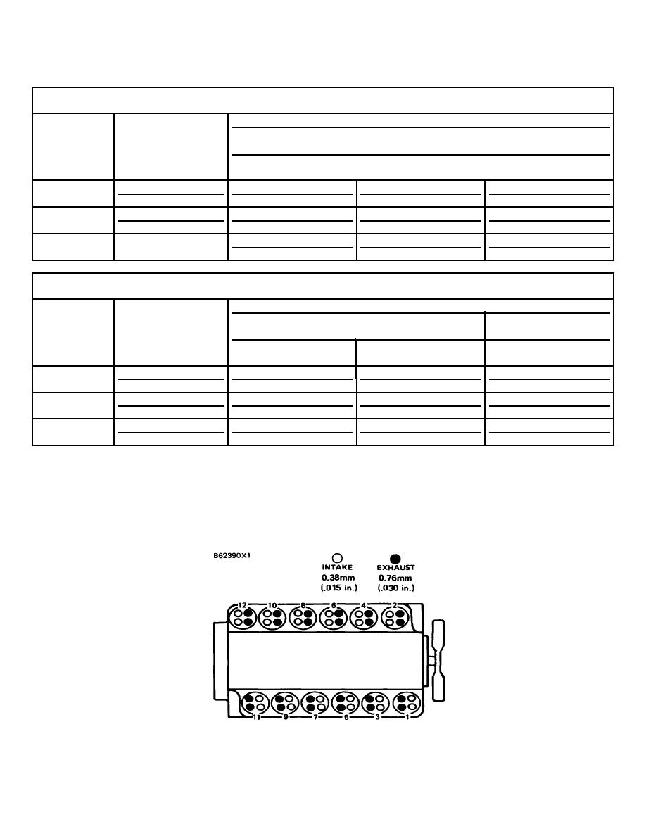
CYLINDER AND VALVE LOCATION
(3512 SHOWN)
136
|
||
 |
||