
| Tweet |

Custom Search
|
|

|
||
 AIR INLET AND EXHAUST SYSTEM
TESTING AND ADJUSTING
3.
Loosen the locknut for the push rod adjustment
VALVE CLEARANCE
screw. If there is not enough clearance for feeler
gauge between rocker arm and bridge contact
Valve clearance (lash) is measured between the
surface,
turn
the
adjustment
screw
rocker arm and the bridge for the valves. All clearance
counterclockwise to increase the valve
measurements and adjustments must be made with the
clearance.
engine stopped, and with the valves FULLY CLOSED.
VALVE CLEARANCE SETTING: ENGINE STOPPED
Valve Clearance Check
VALVES
GUAGE DIMENSION
When the valve clearance is checked,
Intake
0.28 mm (.015 in.)
adjustment is NOT NECESSARY if the measurement is
0.76 mm (.030 in.)
in the range given in the chart for VALVE CLEARANCE
CHECK: ENGINE STOPPED.
However, it is the
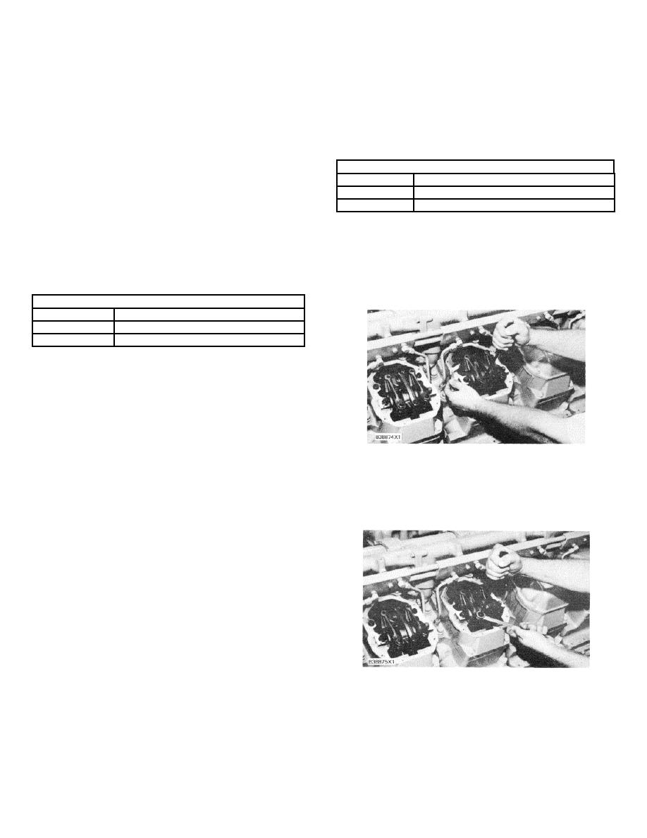
4.
Put a feeler gauge of the correct dimension
recommendation of Caterpillar that the valve clearance
between the rocker arm and bridge contact
setting is to be made at the initial (first) 1000 service
surface. Turn the adjustment screw clockwise
hours of operation, and every 3000 service hours
until the valve clearance is set to the
thereafter.
specifications in the chart VALVE CLEARANCE
SETTING: ENGINE STOPPED.
VALVE CLEARANCE: ENGINE STOPPED
VALVES
ACCEPTABLE CLEARANCE RANGE
Intake
0.30 to 0.46 mm (.012 to .018 in.)
0.68 to 0.84 mm (.027 to .033 in.)
If the measurement is not within this range, or if
the service meter indication is at the specified interval,
adjustment is necessary.
See the subject VALVE
CLEARANCE ADJUSTMENT.
Valve Clearance Adjustment
NOTICE
VALVE CLEARANCE ADJUSTMENT
Due to normal changes (break-in effects) of new or
rebuilt engines, the recommended first interval for
5.
After each adjustment, tighten the nut for the
valve clearance setting is at 1000 service hours of
adjustment screw to a torque of 70 + 15 N-m (50
engine operation.
+ 11 lb. ft.) and check the adjustment again.
Use the procedure that follows for adjustment of
the valves:
1.
Put No. 1 piston at top center (TC) position.
Make reference to FINDING TOP CENTER
POSITION FOR NO. 1 PISTON.
2.
With No. 1 piston at top center position of the
correct stroke, adjustment can be made to the
valves as shown in the chart CRANKSHAFT
POSITIONS FOR FUEL TIMING AND VALVE
CLEARANCE SETTING.
NOTE: Before any actual adjustments are made, tap (hit
TIGHTEN
ADJUSTMENT
SCREW
LOCKNUT
lightly) each rocker arm (at top of adjustment screw) with
a soft hammer to be sure that the lifter roller is seated
against the camshaft base circle.
137
|
||
|
||


