TM 5-2815-241-24&P
ENGINE COMPRESSION BRAKE HOUSING INSTALLATION - CONTINUED
ACTION
LOCATION
ITEM
REMARKS
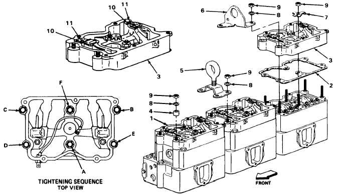
5.
Six new lock
tabs (7)
Using 8-ounce ball-peen hammer, bend
long tab over housing and one short tab
against flat of nut.
6.
Six locknuts (10)
Using 9/16-inch box-end wrench, loosen.
7.
Six adjusting
screws (11)
Using 3/16-inch hex key, unscrew until
slave piston seats in bore.
NOTE
Adjustment must be made with exhaust valves closed. Rotate engine until markings on
accessory drive pulley line up with pointer on gearcase cover and adjust the correspond-
ing cylinder’s adjusting screw.
6.
Six adjusting screws
(11) and six lock-
nuts (10)
a.
Using 3/16-inch hex key and thickness
gage, screw in adjusting screws until
clearance is 0.018-inch (0.46 mm).
b.
Using 3/16-inch hex key and 9/16-inch
box-end wrench, hold adjusting screws
and tighten locknuts.
TASK ENDS HERE
T A 2 4 2 4 0 9
2-117
|
|


