C H AP
142.
5, SEC X VI
Section
D E S C R I P T I ON
R I G H T O U T P U T R E B U I L D
PAR 1 4 2 - 1 4 3
X V I . R I G H T - O U T P U T S U B A S S E M B L Y — R E B U I LD
R e f e r t o p a r . 1 6 f o r d e s c r i p t i o n o f t h e
right-output subassembly.
1 4 3 . D I S A S S E M B L Y ( f i g . 3 8 1 , f o l d - o u t 1 0)
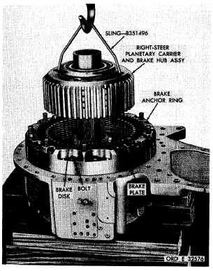
a . Using hoist and sling 8351496, remove
t h e r i g h t - s t e e r p l a n e t a r y c a r r i e r a n d b r a ke
h u b a s s e m b l y ( f i g . 1 5 7 ) . R e f e r t o p a r s . 1 57
through 161 for rebuild of the steer planetary
carrier and brake hub assembly.
N o t e . If carrier and brake hub as-
s e m b l y c a n n o t b e r e m o v e d e a s i l y ,
block up under the end of the carrier
s h a f t , a n d s t r i k e t h e b r a k e a n c h or
ring to free the assembly.
b . R e m o v e t h e r i g h t b r a k e p l a t e s a nd
disks (fig. 157).
Figure 157. Removing (or installing) right-steer
planetary carrier and brake hub assembly
1
2
2
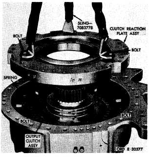
Figure 158. Removing (or installing) clutch reaction
plate assembly
c . Remove 18 bolts (two different lengths),
using a 5/8-inch wrench, retaining the brake
anchor ring (fig. 157).
d . Remove brake anchor ring (fig. 157).
N o t e. Refer to pars. 162 through 166
for rebuild of the right-brake anchor
r i n g a s s e m b l y.
e . U s i n g s l i n g 7 0 8 3 7 7 8 a n d t h r e e 7 / 1 6-
14 bolts, remove the clutch reaction plate as-
s e m b l y ( f i g . 1 5 8 ) . M a r k t h e p l a t e a n d e nd
c o v e r f o r r e f e r e n c e a t r e a s s e m b l y.
f.
Remove
nine
steer
c1utch
release
springs (fig. 158).
g . R e m o v e t w o b o l t s f r o m t h e o u t p u t
clutch assembly (fig. 158).
h . U s i n g s l i n g 7 0 8 3 7 7 8 a n d t w o 5 / 1 6 - 24
b o l t s , r e m o v e t h e o u t p u t c l u t c h a s s e m b ly
(fig. 159).
N o t e . Refer to pars. 167 through 171
for rebuild of output clutch assembly.
|
|