TM 9-2520-272-34&P
4-19.
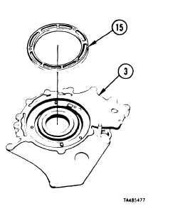
DISASSEMBLE RIGHT END COVER ASSEMBLY
(SHEET 9 OF 16)
17 Turn support (3) over, inside up.
18 Remove stationary cam (15) from support (3).
REPAIR: Refer to paragraph 4-20 for repair of
right brake support assembly.
FOLLOW-ON PROCEDURE: Install right brake support
assembly. Refer to paragraph 4-21.
End of Task 5
TASK 6. REMOVE BRAKE APPLY CAM, BRAKE ADJUSTING LINKS AND
RIGHT BRAKE ASSEMBLY
COMMON TOOLS:
Bar, pry (2 required)
Extension, socket wrench, 1/2 inch square drive, 10 inch
Hammer, hand, plastic faced
Handle, socket wrench, 1/2 inch square drive
Pliers, retaining ring, internal
Screwdriver, flat tip, small
Socket, socket wrench, 1/2 inch square drive, 7/16 inch
Socket, socket wrench, 1/2 inch square drive, 9/16 inch
SUPPLIES:
Rag, wiping
(Rem 15, Appendix C)
NOTE
Right end cover on work table is turned inside up.
Brake apply (rotating) cam, eight balls and brake adjust linkage may come out
with right brake support assembly, or these parts may remain with the right
end cover assembly.
External seal rings (inner and outer) may come out attached to the stationary
cam, or they may remain in the brake apply cam.
Procedures in TASK 6 are based upon above components remaining with right
end cover.
Go to Sheet 10
4-104
Para. 4-19, Task 6
|
|