T M 9 - 2 8 1 5 - 2 0 2 - 3 4
4-26. INJECTOR CONTROL TUBES & THROTTLE DELAY REPLACEMENT
This task covers:
a. Removal
b. Disassembly
c. Cleaning/Inspection
d. Assembly
e. Installation
INITIAL SETUP
MODELS
EXPENDABLE/DURABLE SUPPLIES
n All
Fuel oil (App C, Item 21)
EQUIPMENT CONDITION
TOOLS AND SPECIAL TOOLS
Para Description
General mechanics tool kit (App B, Item 96)
4-11 Rocker arm covers removed
Torque wrench (App B, Item 101)
4-17 Fuel control rods disconnected
MANDATORY REPLACEMENT PARTS
1 Cotter pin (App F, Item 7)
2 Lockwashers (App F, Item 91)
a. Removal
NOTE
Steps (1) and (2) for throttle delay
(1)
(2)
(3)
(4)
assembly only apply to models
7083-7395 and 7083-7396.
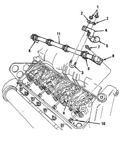
Remove two nuts (1), two
Iockwashers (2), and U-bolt (3) from
throttle delay bracket (4). Discard
Iockwashers.
Remove piston and linkage assembly
(5) from throttle delay housing (6).
Remove four bolts (7) securing
injector control tube brackets (8) to
cylinder head.
Disengage rack levers (9) from
injector control racks (10) and lift tube
assembly (11 ) from cylinder head.
C h a n g e 1
4-93
|
|