TM 9-2815-202-34
e. Installation
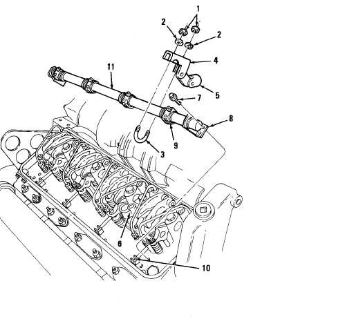
(1) Place injector control tube assembly (11) on cylinder head and install four bolts (7) through
end brackets (8) and into cylinder head. Tighten bolts finger tight. Insure ball end of injector
rack control lever engages in slot of injector control rack. Torque bolts (7) to 10-12 Ib-ft
(14-16 N-m).
(2) Check control tube to be sure it is free in brackets. If necessary, tap control tube lightly to
aline bearing in brackets.
NOTE
Steps (3) and (4) for throttle delay assembly only applies to models 7083-7395 and
7083-7396.
(3)
(4)
Slide throttle delay piston and linkage assembly (5) in bore of housing (6),
Place U-bolt (3) around control tube and through bracket (4). Secure in position with two
nuts (1) and two Iockwashers (2). Tighten nuts to 7-9 Ib-ft (9~12 N-m).
END OF TASK
FOLLOW-ON MAINTENANCE
Para Description
4-17 Connect fuel control rods
4-11 Install rocker arm covers
4-97
|
|


