|
|
|
|

|
TM 9-2815-202-34
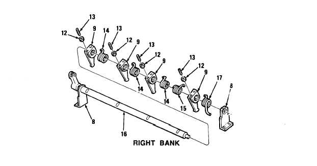
(2) Right bank injector control tube
(a) Install three control levers (9) and three right hand helix yield springs (14) on control
tube (16). Control lever must face front of control tube.
(b)
(c)
(d)
Install left hand helix yield spring (15) and control lever (9) on control tube (16). Control
lever must face front of control tube.
Attach curled end of four yield springs (14 and 15) to four control levers (9) and roll
springs into notch or slots in control tube (16). Turn four adjusting screws (13) with four
nuts (12) into slots far enough to position levers on control tube.
Install control tube return spring (17) and bracket (8) at rear of control tube (16). Attach
curled end of return spring to control lever and extended end of spring behind bracket.
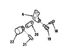
(3) Throttle delay assembly
(a) Connect link (20) to piston (22) with
pin (21).
(b) Connect link (20) to bracket (4) with
pin (19) and cotter pin (18).
4-96
|
|
|
|
|
Privacy Statement -
Copyright Information. -
Contact Us