TABLE 4-2
TM 9-2815-202-34
NOTE
If one bearing shell is less than minimum thickness shown in Table 4-2, replace both
bearing shells (upper and lower).
(c) Using a micrometer and ball attachment, measure thickness of bearing shells (4) at
point "C", 90 degrees from parting line.
(1)
l
l
(2)
(3)
Using micrometer, measure piston
BEARING SHELL CONNECTING ROD THICKNESS
skirt outside diameter parallel and
BEARING
*NEW BEARING
MINIMUM WORN
perpendicular to piston pin bore,
SIZE
THICKNESS
THICKNESS
obtain measurements at room
STANDARD
.1240"/.1245"
.1230"
temperature (70°F-21°C). Diameter
.002” UNDERSIZE
.1250'/.1255'
.1240'
must be 4.2428 to 4.2450 inches
.010” UNDERSIZE
.1290'/.1295'
,1280”
(Diameter above and below pin bore
.020" UNDERSIZE
.1340'/.1345"
.1330”
may be 4.2414 inches).
.030” UNDERSIZE
.1390"/.1395"
.1380”
‘Thickness 90° from parting line of bearing.
NOTE
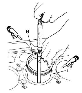
Use feeler gage to check piston skirt to liner clearance. Use a spring scale attached
to feeler gage to measure amount of force in pounds required to withdraw feeler
gage from between piston and liner. Select feeler gage with thickness that will
require six pounds pull to move. Piston to liner clearance will be 0.001 inch greater
than thickness of feeler gage used. For example, a 0.004 inch feeler gage indicates
0.005 inch clearance when withdrawn with a six pound pull.
Feeler gage must be perfectly flat and free of nicks and bends.
With cylinder liner (1) installed in
cylinder block, hold piston skirt (14)
upside down in liner and check
clearance in four places 90 degrees
apart. Clearance must be 0.0045 to
0.0083 inch with new parts. Maximum
clearance of 0.012 inch is allowed for
used parts.
If binding occurs between piston and
liner, remove piston and examine
piston and liner for burrs. Remove
burrs with fine flat hone and recheck
clearance.
Change 1
4 - 1 37
|
|


