TM 9-2815-202-34
4-33. PISTON AND CONNECTING ROD MAINTENANCE (CROSS-HEAD) (Cont)
f. Fitting Piston Rings
(1)
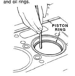
Insert top piston ring inside cylinder liner in normal area of ring travel. Use a piston skirt to
push ring down to insure ring is parallel with top of liner. Measure ring gap with feeler gage.
Refer to Table 4-3 for ring gap specifications. Repeat procedure for balance of compression
CAUTION
File or stone both ends of
compression ring from outer surface
to inner surface to prevent chipping
or peeling of chrome plating on ring.
Ends of ring must remain square,
and chamfer on outer edge must be
approximately 0.015 inch.
TABLE 4-3 PISTON RING SPECIFICATIONS
GAP (NO.2, AND 3)
CLEARANCE RING TO GROOVE:
TOP RING
NO.2
NO03
OIL CONTROL RINGS
GAP (TWO RINGS IN
LOWER GROOVE)
GAP (ONE RING IN
UPPER GROOVE)
CLEARANCE (TWO RINGS
IN LOWER GROOVE)
CLEARANCE (ONE RING
IN UPPER GROOVE)
MINIMUM
MAXIMUM
.0230 IN (.0286CM
.0380 IN. (.0965CM)
.0180 IN. (.0457CM)
.0430 IN. (.1092CM)
.C080 IN. (.0025CM)
.0050 IN (.0127CM)
,0100 IN. (.0254CM)
.0130 IN (.0330CM)
.0040 IN. (.0101CM)
.0070 IN. (.0177 CM)
.0080 IN (.0203CM)
I
.0230 IN. (.0584CM)
.0050 IN. (.0127CM)
.0140 IN. (.0356CM)
.)015 IN. (.0038CM)
.0055 IN. (0139CM)
.0010 IN. (.0025CM)
.0040 IN (.0101CM)
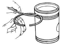
(3) Using feeler gage, measure ring side
clearance by inserting edge of ring in
appropriate groove of piston.
Refer to Table 4-3 for ring side
clearance specifications.
g. Assembly
(1) Piston and Rod Assembly
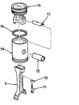
(a) Install pin bushing (17) in piston
dome (15). It should slide into
piston dome without force.
NOTE
Soak seal rings in engine oil for 15
minutes prior to installation on
dome.
(b) Lubricate seal ring (16) and
install in groove on piston dome
(15).
Change 1
4-138
|
|


