(4)
(5)
(6)
(7)
(8)
(9)
(10)
(11)
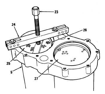
Support one end of oil cooler
assembly (5) on blocks. Attach puller
(23) to oil cooler assembly and place
bar tooI (24) on upper tube bundle
(25).
Press upper tube bundle (25) down
enough to remove seal (26) from oil
cooler assembly (5). Remove puller
(23) and bar tool (24). Discard seal.
Invert oil cooler assembly (5). Using
puller (23) and bar tool (24), press
upper tube bundle (25) down enough
to remove remaining seal (26) from oil
cooler shell. Remove puller, bar tool,
and upper tube bundle. Discard seal.
Repeat steps (4, 5, and 6) for lower
tube bundle (27).
T M 9 - 2 8 1 5 - 2 0 2 - 34
Remove seven bolts (28), seven Iockwashers (2), oil return junction (29), and gasket (30)
from rear cover (21). Remove oil return junction. Discard Iockwasher and gasket.
If necessary, remove two plugs (31) and seven plugs (32) from cooler shell (33).
If necessary, remove drain cock (34) from rear cover (21).
If necessary, remove four bolts (28), four Iockwashers (2), and support bracket (35) from
cover (21). Discard Iockwashers.
c. Cleanlng/inspection
(1)
(2)
(3)
(4)
Inspect front and rear oil cover, access cover, and oil cooler shell for cracks or damage.
Using spring tester (36), check valve spring (11) load. Replace spring if it compresses to
length of 0.813 inch (20.65 mm) with a 6.5 lb load.
Inspect retainer for cracks, warps, or damage.
Inspect tube bundles for damaged baffles, cracks, or plugged tubes.
d. Assembly
(1)
(2)
(3)
(4)
(5)
rear
a
If removed, instaIl support bracket (35) to rear cover (21). Secure with four bolts (28) and four
Iockwashers (2). Torque bolts to 30-35 Ib-ft (41-47 N-m).
If removed, install drain cock (34) into rear cover (21).
Secure gasket (30) and oil return junction (29) to rear cover (21) with seven bolts (28) and
seven Iockwashers (2). Torque bolts to 30-35 Ib-ft (41-47 N-m).
If removed, install two plugs (31) and seven plugs (32) into oil cooler assembly (5). Tighten
securely.
Support one end of oil cooler assembly (5) on blocks.
4-219
|
|


