TM 9-2815-202-34
4-40. FUEL INJECTOR ASSEMBLY REPAIR (Cont)
(13)
(14)
(15)
(16)
(17)
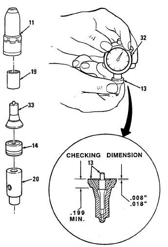
Spray tip
(a)
(b)
Check spray tip (33) for cracks,
enlarged spray holes, corrosion
on outside diameter taper, and
oxide scale on spray hole end.
Check nut to tip sealing surface
and lapped sealing surface for
scratches. Do not reuse if there is
scale, cracks, or enlarged spray
holes.
Measure thickness of spray tip
shoulder. Minimum thickness is
0.199 inch.
Needle valve
Check spray tip needle valve for
erosion at seat shoulder, scratches,
and overheating.
Needle valve lift
Using needle valve height gage (32),
measure needle valve lift as follows:
(a) Zero indicator by placing bottom
surface of plunger assembly on a
flat surface and zero indicator
dial.
(b) Place spray tip and needle valve
assembly (13) tight against
bottom of gage with quill of
needle valve in hole in plunger.
(c)While holding spray tip and needle
valve assembly (13) tight against gage
(32), read needle valve lift indicator. Lift
should be 0.008 to 0.018 inch. If tip
assembly exceeds 0.018 inch, replace
it. If less than 0.008 inch, inspect tip
assembly for foreign material between
needle valve and tip seat.
Nut
Check nut (11 ) for damaged threads, condition of seal ring seating area, and condition of
spray tip seating area. Check spray tip hole for corrosion.
Spill deflector
Inspect ends of deflector (19) for sharp edges or burrs.
4-228
Change 1
|
|