TM 9-2815-202-34
4-40. FUEL INJECTOR ASSEMBLY REPAIR (Cont)
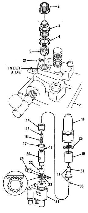
e. Assembly
(1) Secure injector body (21) infolding fixture(1).
(2) install filter (5) in inlet port of body (located above injector rack). Position filter with dimple end
down and slotted end up. No filter is required at outlet port.
(3) Install two gaskets (4) and two fuel connectors (3) to injector body. Lubricate connector threads
with engine oil before installation. Torque connectors to 70 Ib-ft (95 N-m) (blued components)
or to 62 Ib-ft (84 N-m) (mixed and nonblued components).
(4) Install two shipping caps (2) to connectors (3) to prevent dirt from entering injector.
(5) Support injector body assembly, bottom
end up, in holding fixture.
(6) Install seal ring (25) onto shoulder of
injector body (21 ).
(7) Slide injector control rack (24) into injector
body (21 ).
(8) Look into injector body bore and move
control rack (24) until you see two drill
marks on rack. Hold rack in this position.
(9) Place gear (23) in injector body so that
marked tooth on gear is engaged between
two marked teeth on control rack (24).
(10) Place gear retainer (22) on top of gear (23).
(11) Aline locating pin in bushing (20) with slot in
injector body (21). Slide end of bushing into
place.
(12) Install spill deflector (19) over barrel of
bushing (20).
NOTE
Perform needle valve opening
pressure test [ref. step f.(5)] at this
time before completing assembly.
(13) Place check valve (18) centrally on top of
bushing (20).
(14) Place check valve cage (17), flat side up,
over check valve (18) and against bushing
(20). Check valve cage must not rest on
check valve.
(15) Insert spring seat (15) in valve spring (16).
Install assembly on check valve cage (17)
with seat up.
4-230
Change 1
|
|