(16)
(17)
(18)
(19)
(20)
(21)
(22)
(23)
(24)
(25)
TM9-2815-202-34
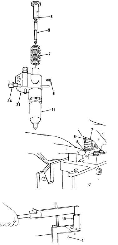
Place spring cage (14) over spring seat (15) and spring (16).
Insert needle valve (35) into spray tip (33) with tapered end down. Place spray tip assembly
(13) on top of spring cage (14) with quill end of needle valve in hole in spring cage.
Lubricate threads on injector nut (11) with engine oil and carefully thread nut on injector
body. Tighten nut as tight as possible by hand.
Turn injector over and push rack (24) all way in.
Place follower spring (7) on injector body
Slide head of plunger (9) into follower
(8).
Aline slot in follower (8) with stop pin
hole in injector body (21).
Aline flat side of plunger (9) with flat in
gear.
Insert free end of plunger (9) in
injector body (21).
Place stop pin (6) in slot on injector
body (21 ). Rotate spring (7) so flat
part of end coil is clear of pin (6).
Then push pin in place while pressing
down on follower (8). Once in place,
rotate spring (7) so flat on end coil is
positioned over pin.
CAUTION
Do not exceed specified torque. Otherwise,
nut may be stretched and result in improper
sealing of lapped surfaces in overhauled
injector.
NOTE
After assembling fuel injector,
always check area between nut and
body. If seal is still visible after nut is
torqued, try another nut and seal.
(21).
(26) With injector in holding fixture (1) and
using injector nut socket (10), torque
injector nut (11) to 80 Ib-ft (108 N-m)
for blued components or 50 Ib-ft
(68 N-m) for nonblued components or
65 Ib-ft (88 N-m) for mixed
components.
4-231
|
|