(15.1)
(16)
(17)
(18)
TM 9-2815-202-34
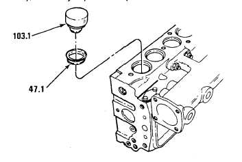
For model 7083-7391 only, if necessary, install eight exhaust port seals (47.1) in cylinder head.
Using hammer and exhaust seal installer (103.1), carefully tap seal in place.
NOTE
l
l
Models 7083-7396 and 7083-7391
contain four bolts (33), four flat
washers (34), two cover plates
(35), and two gaskets (36) per
head and no cover plate on rear
inboard corner.
Model 7083-7399 contains six
bolts (33), six flat washers (34),
three cover plates (35), and three
gaskets (36) per head.
Install gaskets (36), cover plates (35), flat washers (34), and bolts (33) to remaining
cylinder head. Torque bolts to 7-9 Ib-ft (10-12 N-m).
corners of
If necessary for models 7083-7396 and 7083-7399, install support bracket (37), two
Iockwashers (39), and two bolts (3$) to right cylinder head. Torque bolts to 30-35 Ib-ft (41-47
N-m).
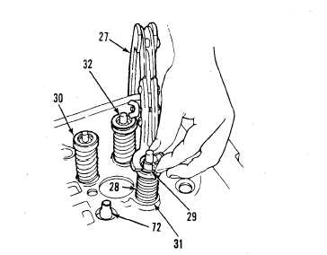
Install sixteen exhaust valves as follows:
(a)
(b)
(c)
(d)
(e)
(f)
Position cylinder head on its side. Lubricate valve stems with sulphurized oil (E. P. type) and
slide valves (32) all the way into guides (72).
With
Install lower spring
NOTE
used valves, install in their original location.
seat (31 ), valve spring (28), and upper spring
seat (30) over valve stem.
CAUTION
Avoid scoring valve stem with valve seat when compressing spring.
Using valve spring compressor (27),
compress valve spring (28) and install
two piece tapered valve locks (29).
Release pressure on valve spring
compressor (27) and remove tool.
Repeat steps (a) thru (d) for remaining
valves.
Support cylinder head on wood blocks
at both ends (right side up). Give end of
valve stems a sharp tap with soft
headed hammer to seat valve locks
(29).
Change 1
5-59
|
|