TM 9-2815-202-34
(16)
(17)
(18)
(19)
(20)
(21)
(22)
(23)
(24)
(25)
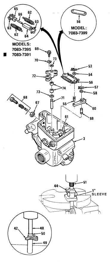
Insert control link operating Iever (72)
and two washers (73) between two
bosses inside governor housing (3).
Install operating lever shaft (71) with
grooved end up.
Install locking clip (70) and screw and
washer assembly (69) securing
operating lever shaft in governor
housing (3). Tighten screw (69)
securely.
Install buffer screw assembly (68) and
locknut (67).
Place governor housing (3) in soft-
jawed vise.
For models 7083-7391 and 7083-7396
only, assemble pin (66), governor link (64),
and link (65) together. Install two retainer
clips (63) and two springs (62).
If removed, install pin (55) into
differential lever (60).
Install differential lever (60), washer
(58), and spring clip (57) on operating
lever (61 ) with slot facing rear of
governor housing (3).
Install operating lever connecting link
(56) on differential lever (60) and
secure with washer (54) and retaining
clip (53) to pin (55).
Using an arbor press and one-inch
inside diameter sleeve, press weight
shaft (51) into weight carrier (44) until
shoulder of weight shaft is seated in
carrier.
NOiTE
When installing weights, insure
matchmarks made at disassembly
are alined.
(26)
Lubricate outside diameter of needle
bearing (50) with engine oil and
inside diameter with grease. Using
bearing installer (48), sleeve (49) and
arbor press, install needle bearing
(50) into high speed weight (42).
Repeat procedure for other high
speed weight (42).
Change 1
5-71
|
|