TM9-2815=202-34
8-7. FUEL INJECTOR CONTROL LEVER ADJUSTMENT
This taskcovers: Adjustment
l
INITIAL SETUP
EQUIPMENT CONDITION
MODELS
Para Description
, All
4-11 Rocker arm covers removed
8-6 Throttle delav disconnected
18-6
TOOLS AND SPECIAL TOOLS
8-6
General mechanics tool kit (App B, Item 96)
8-6
8-6
MANDATORY REPLACEMENT PARTS
(7083-7395 and 7083-7396)
Starting aid screw backed out
(7083-7391, 7083-7395, and 7083-7396)
Governor spring housing removed
l
(Dual range limiting speed governor)
Governor spring housing removed
(Limiting speed governor)
Buffer screw backed out
2 Cotter pins (App F, Item 7)
Adjustment
LEFT BANK
.
l
l
NOTE
To ensure proper injector control
rack adjustment, adjust injector
control racks with yield link and
governor cover used with
governor.
Letter “R” or “L” indicates
injector location, right or left bank,
as viewed from rear of engine.
Cylinder numbers start at front of
each bank.
HF”NT
Adjust No. 1 L injector control
l
lever first to establish a guide for
adjusting remaining injector
control levers.
l
A false fuel injector rack setting
may result if idle speed adjusting
screw is not backed out.
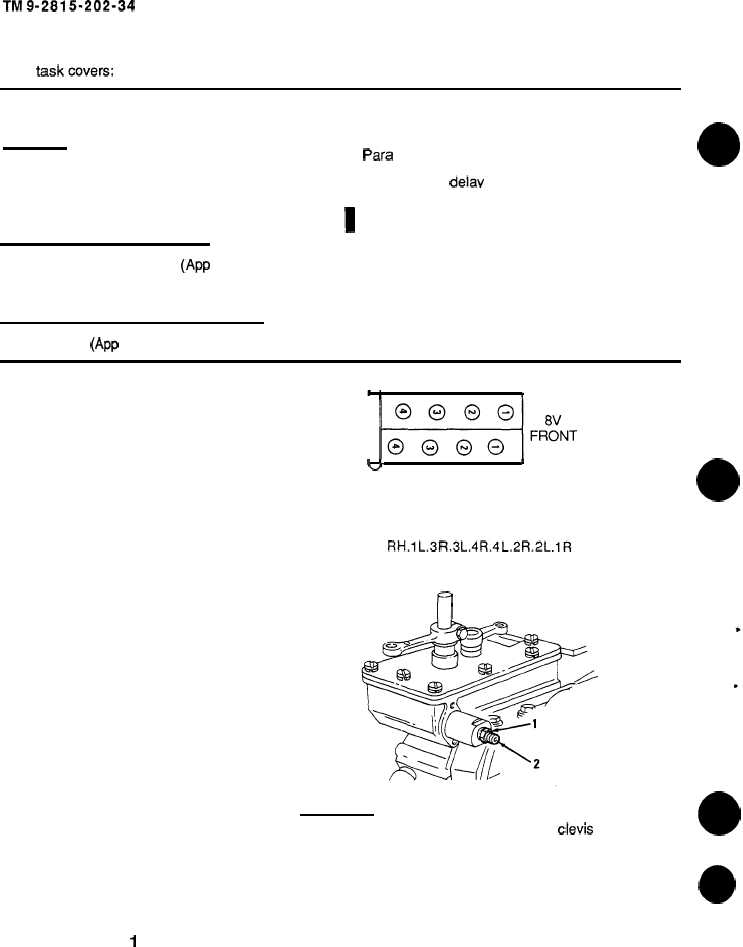
a. Loosen and hold locknut (1). Turn idle
speed adjusting screw (2) until 0.5 inch of
threads project from locknut.
CAUTION
\
b
I
u
RIGHT BANK
FIRING
ORDER
RH.1L.3R.3L.4R.4 L.2R.2L.1R
n
Cover oil drain hole in cylinder head with clean rag to prevent cotter pin and clevis pin
from falling into engine.
8-16
Change 1
|
|