l
b.
c.
l
d.
e.
f.
9.
h.
i.
l
TM9-2815-202-34
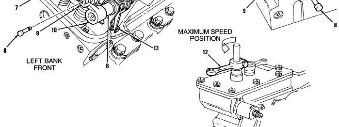
Loosen eight rack control lever locknuts (3) and back out eight adjusting screws (4). Eight injector
control levers (5) should be loose on control tubes (6).
Move linkage (7) connecting governor to control racks. Linkage must not bind.
Rotate clevis pins (8) in right and left bank control tube levers (9). Pins must rotate freely.
Check for slight movement between brackets (1 O), at each end of control tubes (6), on right and
left banks.
Rotate control tube lever (9) to FULL FUEL position; then release lever (9). Control tube must
return to NO FUEL position.
Remove cotter pin (11 ) and clevis pin (8) from right bank control tube Iever (9). Discard cotter pin.
Move governor speed control lever (12) to maximum speed position and hold with light finger
pressure.
CAUTION
Do not overtighten injector rack control lever adjusting screws during installation or
adjustment. Overtightening can result in damage to injector control tube.
Recommended torque of adjusting screws is 24-36 lb-in (3-4 N-m).
Turn adjusting screw (4) on 1 L injector rack control lever until slight movement is felt on governor
speed lever (12), injector control rack (13) rolls up on control lever (5), or an increase in effort to
turn screw (4) is felt.
7%=2(’(IL
8-17
|
|


