
| Tweet |

Custom Search
|
|

|
||
 TM 9-2815-220-24
THROTTLE ADJUSTMENTS
THIS WORK PACKAGE COVERS:
Before Adjustment and Adjustment
INITIAL SETUP:
Tools:
Personnel Required:
General mechanic's tool kit (item 121, WP 0176)
Track Vehicle Repairer (2) 63H10
Equipment Conditions:
Engine removed from vehicle and placed on a
flat stationary surface
BEFORE ADJUSTMENT
1. Check throttle control adjustable rod (1), manual fuel shutoff rod (2), and throttle operating
lever rod (3) for free movement.
a. If linkage moves freely, proceed to Adjustment; if not, go to Throttle Control and Manual
Fuel Shut-off Replace/Repair (WP 0122) for Model 2CA and 2DA engines and Throttle
Control Solenoid Assembly and Associated Parts Replace/Repair (WP 0123) for 2DR
engines.
ADJUSTMENT
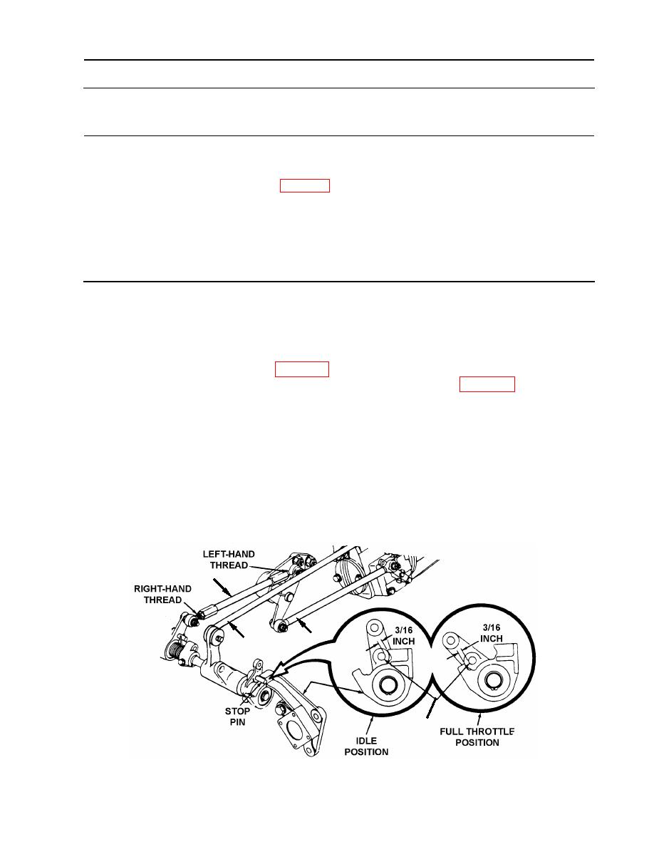
1. Stop pin (4) adjustment (all engine models).
a. With engine stopped, check clearance between stop pin (4) and stops at both ends of travel.
Clearance must be a minimum of 3/16 inch (0.1875 mm) at each end of travel.
b. If clearance is not 3/16 inch (0.1875 mm) at both ends of travel, loosen lock nuts on
throttle control adjustable rod (1), and adjust rod as necessary to obtain required clearance.
c. Tighten lock nuts after adjustment.
1
3
2
4
WP 0043 00-1
|
||
|
||


