
| Tweet |

Custom Search
|
|

|
||
 TM 9-2815-220-24
FUEL INJECTION TUBES REPLACEMENT
0113 00
INSTALLATION (Continued)
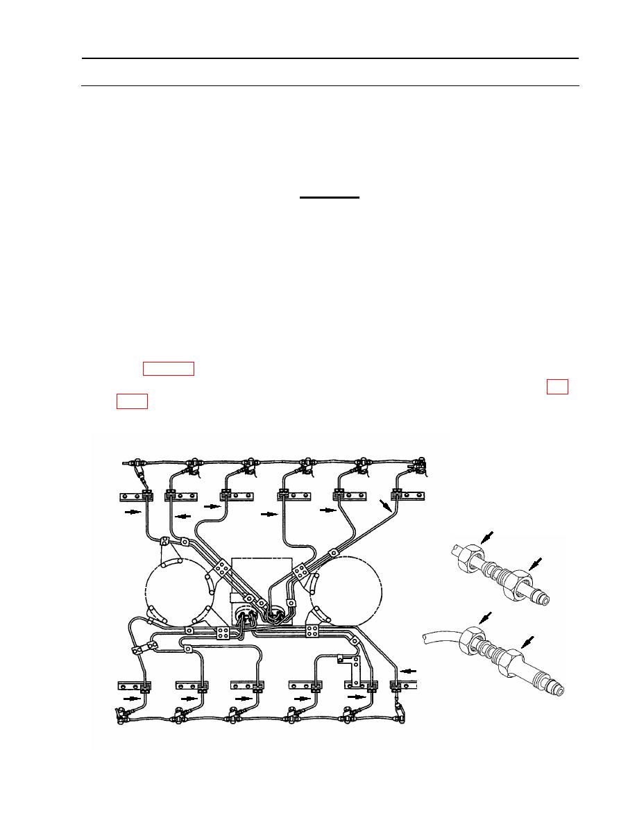
1. Install fuel injection tubes (4-15) in 4R, 1R, 2R, 6R, 3R, 5R, 3L, 5L, 6L, 1L, 2L, and 4L
sequence, starting at the fuel injection pump end for each tube. Complete the following steps
for each tube assembly in sequence: (Continued).
CAUTION
Over tightening will damage the compression sleeve and cause fuel
leaks. Over tightening can fracture the sleeve and result in injector
tube failure. Tube assemblies must be visually aligned between the
bolt holes on the cylinder head mounting brackets. Hold the lines in
this aligned position while torque tightening the compression
connectors at the pump end of the tubes.
The compression connector (3) must be held in place while tightening
the support nut (1). Failure to comply may result in damage to fuel
injection tubes.
c. Tighten compression connector (3) to 35 foot-pounds (48 Nm) using torque wrench (item
127, WP 0176).
e. Attach compression nut (2) and support nut (1) to the nozzle and tighten finger-tight.
1R
3R
2R
6R
5R
4R
Right Bank
9
6
8
4
7
5
1
2
Damper
End
1
3
15
14
10
11
12
13
Left Bank
3L
2L
5L
4L
1L
6L
WP 0113 00-5
|
||
|
||


