| Tweet |

Custom Search
|
|

|
||
 TM 9-2815-220-24
CYLINDER ASSEMBLY REPLACEMENT
0133 00
REMOVAL (Continued)
5. Rotate maintenance stand so that cylinder assemblies are vertical.
NOTE
For ease of disassembly, the following pistons are at top center
together: (1 & 6) (2 & 5) (3 & 4) on either bank.
6. Position piston (6) in cylinder for removal.
a. Rotate crankshaft and observe when connecting rod has raised the piston to top center.
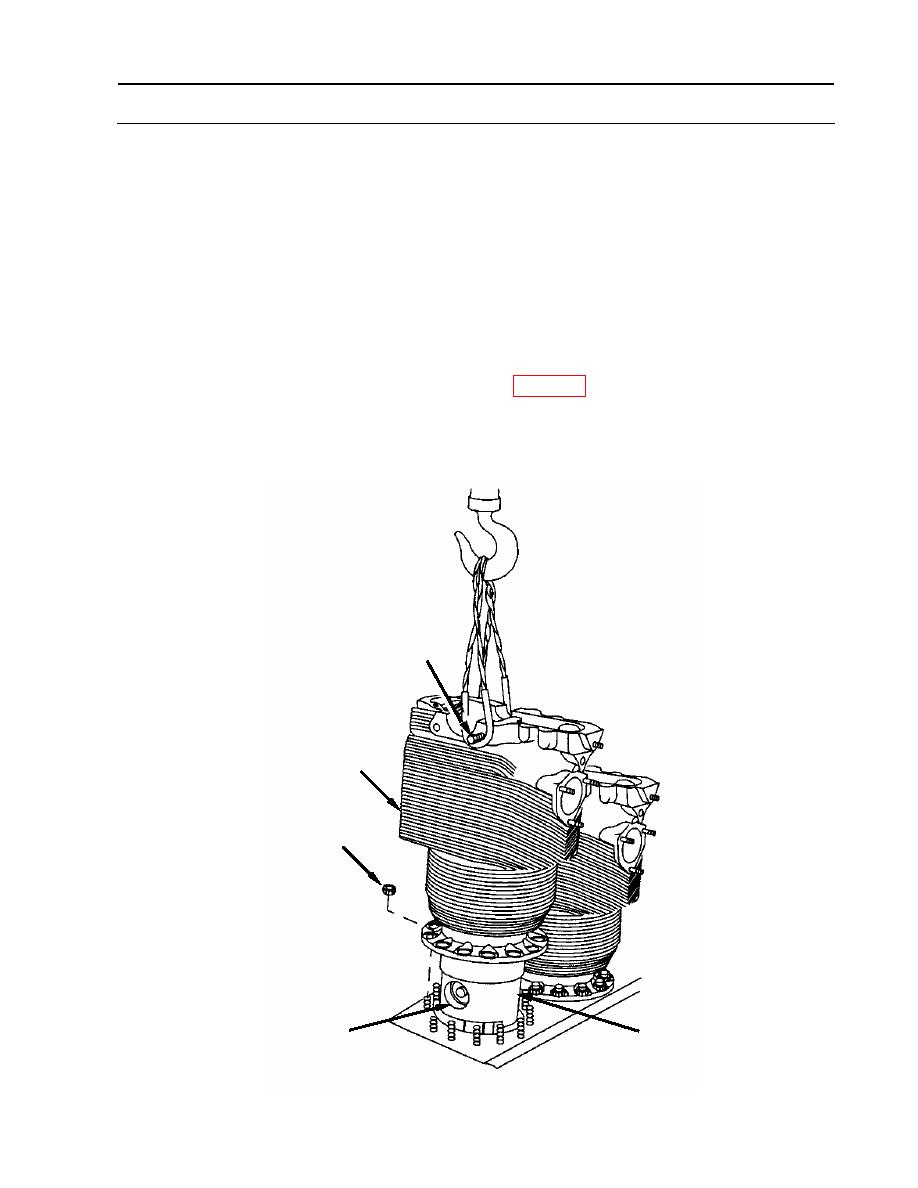
7. Remove cylinder assembly (1).
a. Attach a suitable lifting sling to top of cylinder assembly using two 7/16 x 1-1/4 inch cap
screws (7), then attach to lifting sling (item 18, WP 0176).
b. Remove last two cylinder base nuts (2).
c. Carefully lift cylinder assembly until it is just above piston pin bore (A).
7
1
2
A
6
WP 0133 00-5
|
||
 |
||