
| Tweet |

Custom Search
|
|

|
||
 TM 9-2815-220-24
CRANKSHAFT REPLACE/REPAIR
0139 00
INSTALLATION (Continued)
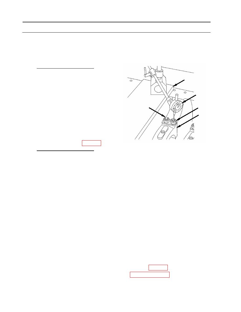
10. Tighten main bearing cap (6) nuts (8).
a. Make sure that nuts are loose (6), then
measure and record the height of four
main bearing cap studs (28) at number 4
location. Use a flat surface plate (30) and
30
dial indicator (27).
27
b. At number 4 main cap (6), in a
crosshatch pattern, torque-tighten four
28
8
slotted nuts (8) to 42 foot-pounds
(57 Nm). Using the same crosshatch
6
pattern, torque-tighten the same four nuts
(8) to 58 foot-pounds (79 Nm).
c. Using a flat surface plate (30) and dial
indicator (27) (item 65, WP 0176),
measure and record the height of four
main bearing cap
studs (28) at number 4 location. Subtract
the first reading from the second, this is
the stud stretch.
d. Tighten nuts (8) to align with safety wire hole in stud and attain a stretch of 0.019 to 0.024
inch (0.4826 to 0.6096 mm).
e. Any stud that exceeds the maximum stretch (0.024 inch, or 0.6096 mm) prior to the nut
obtaining minimum torque (58 foot-pounds, or 79 Nm) must be replaced.
f. Any stud that its nut reaches maximum torque (69 foot-pounds, 94 Nm) prior to obtaining
minimum stretch (0.019 inch, or 0.4826 mm) may be loosened and tried again. Loosening
of a single nut is not allowed; all nuts on that bearing cap must be loosened. If the
condition exists after the second try, the stud must be replaced.
g. Repeat for remaining caps in the following order 3,5,2,6,1, and 7.
h. Secure 28 slotted nuts (8) with new lock wire (7) (item 44, WP 0173).
11. Install accessory drive gear and oil seal housing (see Work Package 0158).
WP 0139 00-22
|
||
|
||


