
| Tweet |

Custom Search
|
|

|
||
 TM 9-2815-220-24
STARTER DRIVE MECHANISM REPAIR
0157 00
REMOVAL (Continued)
2. Remove spur gear (5) (Continued):
b. Install three 5/16-24 X 3-inch bolts (8) (item 12, WP 0176), for use as puller screws, into
threaded holes provided in spur gear (5).
c. Alternately tighten bolts (8) to pull spur gear (5) from spur gear shaft (7).
d. Remove three puller screws (8) from spur gear (5).
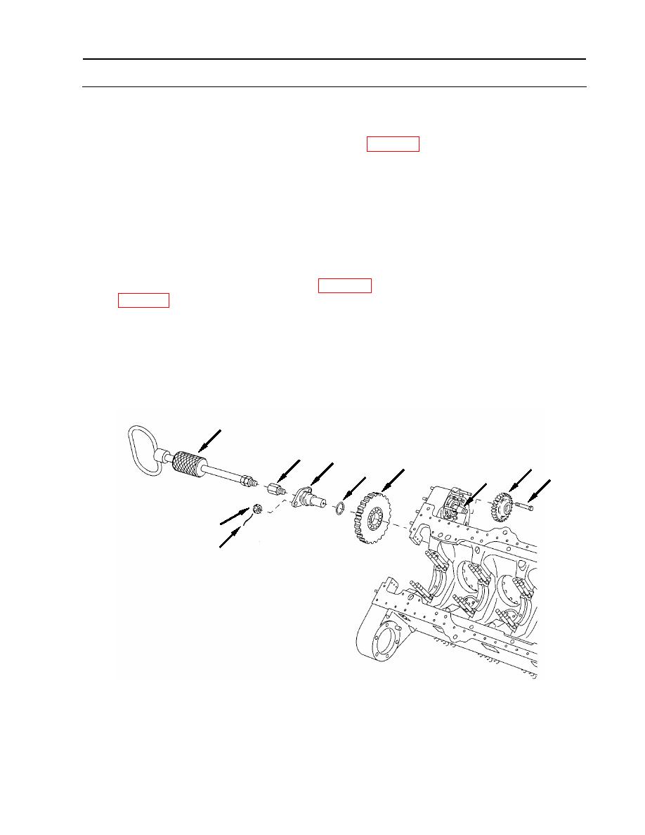
3. Remove idler spur gear (9).
a. Cut and remove locking wire (10) and remove two slotted nuts (11) securing idler
shaft (12).
b. Attach mechanical adapter (13) (item 2, WP 0176) and slide hammer puller (14) (item 88,
c. Support idler gear (9) while using slide hammer puller (14) to remove idler shaft (12).
d. Remove O-ring (15) from idler shaft (12). Discard O-ring.
e. Remove slide hammer puller (14) and adapter (13) from idler shaft (12).
14
13
12
9
5
15
8
7
11
10
WP 0157 00-3
|
||
|
||


