
| Tweet |

Custom Search
|
|

|
||
 TM 9-2815-220-24
STARTER DRIVE MECHANISM REPAIR
0157 00
REMOVAL (Continued)
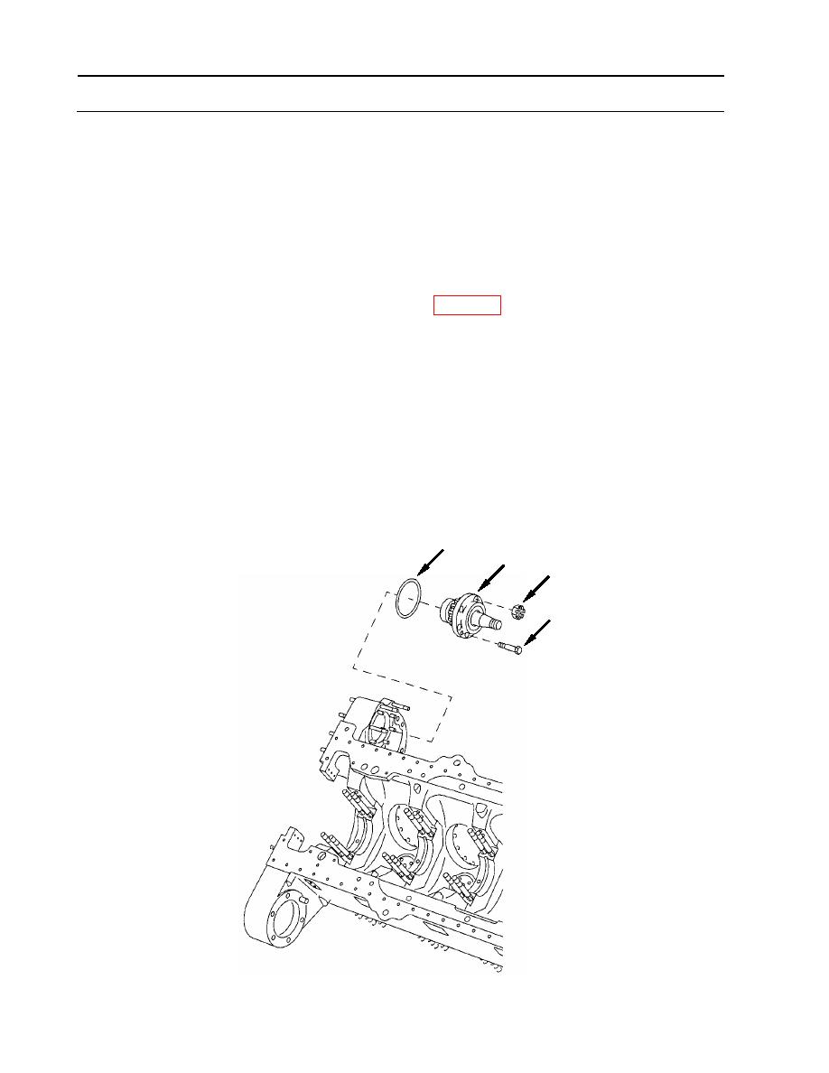
4. Remove bearing housing (16).
NOTE
Retaining nuts may be slotted and secured with cotter keys, if so
remove and discard. Self-locking nuts will be used on assembly.
a. Remove six self-locking nuts (17) securing bearing housing (16). Discard nuts.
b. Install two 5/16-24 X 3-inch bolts (8) (item 12, WP 0176), for use as puller screws, into
threaded holes provided in bearing housing (16).
c. Alternately tighten bolts (8) to pull bearing housing (16) from crankcase.
d. Remove and discard O-ring (18).
e. Remove two puller screws (8) from bearing housing (16).
18
16
17
8
WP 0157 00-4
|
||
|
||


