| Tweet |

Custom Search
|
|

|
||
 TM 9-2815-226-34-1
(5) Add shim(s) beneath liner flange as needed to establish a 0.003 in. (0.076 mm) minimum to 0.006 in.
(0.152 mm) maximum protrusion. Shims are available in 0.007, 0.008, 0.009, 0.020, 0.030, and 0.062 in.
(0.177, 0.203, 0.228, 0.508, 0.762, and 1.574 mm) sizes.
(6) Reinstall liner with appropriate size shims.
(7) Reclamp liner and retorque clamp capscrews to 50 ft lbs (68 N m).
Remeasure protrusion to insure
dimensions are within specifications.
(8) Remove gage block and dial indicator, clamps, and liner.
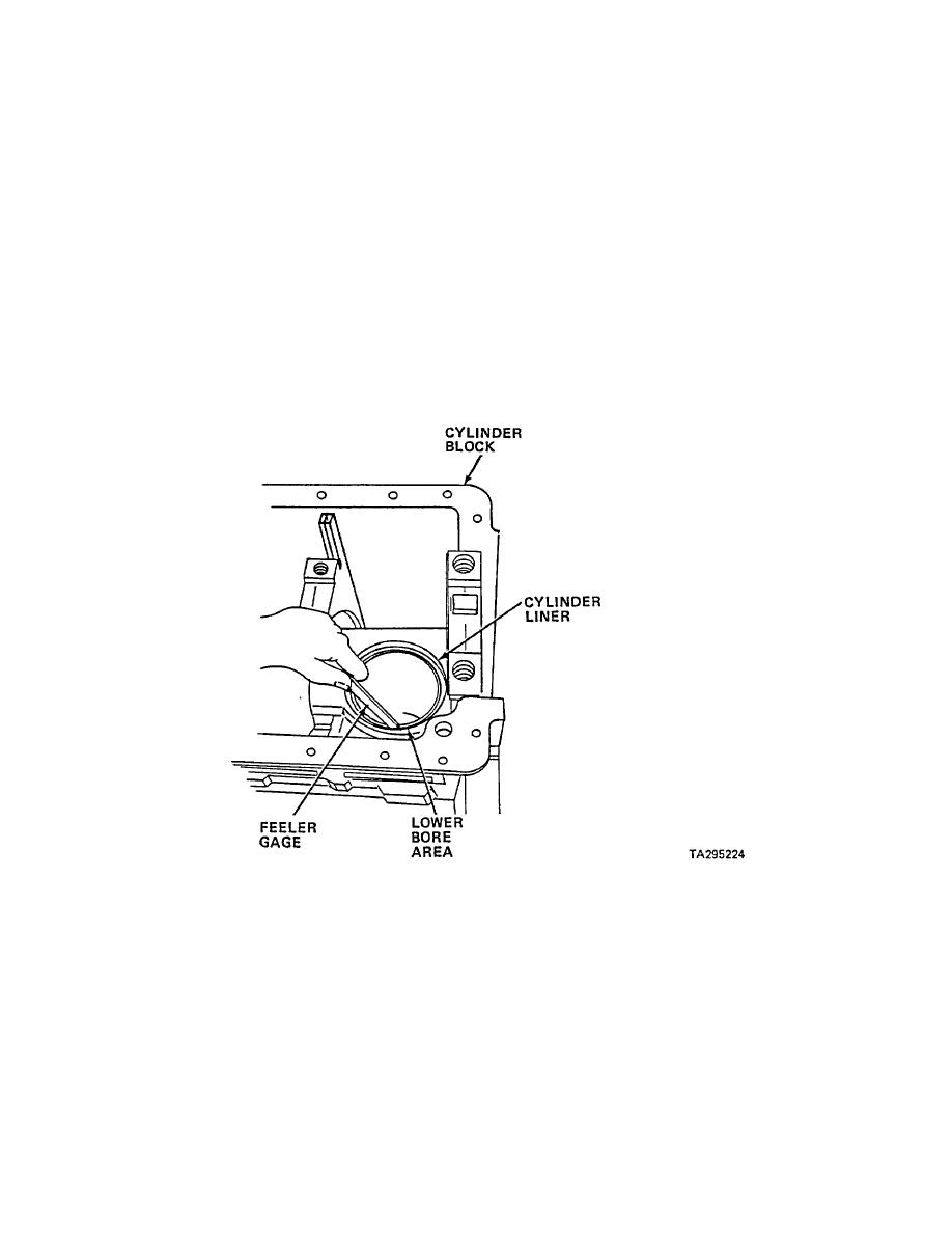
k. Check cylinder liner lower counterbore.
(1) Install new liner without shims or seals into cylinder block and clamp liner in position.
Torque clamp
capscrews to 50 ft lbs (68 Nm).
(2) Measure clearance between cylinder block and liner lower counterbore with narrow leaf feeler gage. Liner
contact with block is permitted providing it does not cause liner out-of-round.
(3) If clearance exceeds 0.006 in.
(0.152 mm), remove liner and measure inside diameter of lower
counterbore.
(4) If lower counterbore diameter exceeds 6.126 in. (155.600 mm), counterbore must be machined to accept
replacement sleeve. Sleeve is available in two sizes; 6.2555 in. (158.889 mm) and 6.3055 in. (160.1597
mm).
3-64
|
||
 |
||