TM 9--2815--247--34
0037 00--13
FUEL INJECTOR TUBES, BRACKETS, AND ASSOCIATED PARTS --
CONTINUED
0037 00
Installation -- Continued
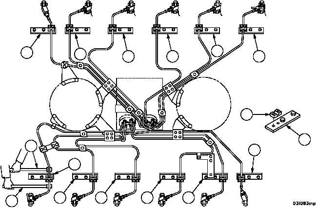
24. Inspect all tube assemblies for 1/8 inch (3.175 mm) minimum clearance to each other at pump end. Bend tubes
as required with bending tools (72) to obtain clearance.
NOTE
When bending of tube assemblies is required at the pump
end, the tube fitting and tube nut must be retorqued. Re-
fer to d.3.
25. Install 12 lower fairlead halves (45) between tube assemblies and spacer plates (46).
CAUTION
Where bending tubes is required, be careful not to nick
tubing. The bending tools are designed to allow bending
without nicks.
26. Using two bending tools (72), align tubes to fit within 1/8 inch (3.175 mm) in any direction with fairlead halves,
which should be aligned with spacer plate bolt holes.
Figure 36
RIGHT BANK
LEFT BANK
DAMPER
END
FLYWHEEL
END
45
46
46
46
46
46
46
46
46
46
46
46
46
72
72
46
|
|