|
|
|
|

|
TM 9--2815--247--34
0070 00--8
CONNECTING ROD ASSEMBLY AND ASSOCIATED PARTS REPAIR --
CONTINUED
0070 00
Inspection -- Continued
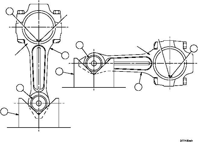
15. Check connecting rod assembly (9) for parallelism and twist by setting in V--blocks (18) using a new piston pin
(19) and measuring bearing from side to side with a dial indicator. Replace rod assemblies that do not meet the
following limits.
REF
NO.
POINT OF MEASUREMENT
WEAR LIMITS WITH NEW
PISTON PIN BUSHING
WEAR LIMITS WITH USED
PISTON PIN BUSHING
20
Parallelism of connecting rod
0.0005 (0.0127) per inch of
bearing width
0.0010 (0.0254) per inch of
bearing width
21
Twist of connecting rod
0.0010 (0.0254) per inch of
bearing width
0.0010 (0.0254) per inch of
bearing width
Figure 8
20
9
19
18
18
19
9
21
INDICATE
HERE
INDICATE
HERE
LIP SIDE
LIP SIDE
SETUP ”A”
PARALLELISM
SETUP ”B”
TWIST
NOTE: ZERO INDICATOR ON LIP SIDE.
READ INDICATOR ON OPPOSITE SIDE.
|
|
|
|
|
Privacy Statement -
Copyright Information. -
Contact Us