TM 9--2815--247--34
0076 00--8
CAMSHAFT, DRIVE GEARS, AND ASSOCIATED PARTS REPAIR --
CONTINUED
0076 00
Assembly
NOTE
It will be necessary to move the camshaft drive gear
away from the camshaft driven gear to gain clearance for
installation of camshaft assembly.
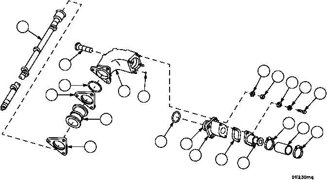
1. Install bevel gear shaft (6) and camshaft assembly (30) into mechanical housing (31).
2. Install new gasket (29) and straight adapter (23) on camshaft adapter (22) with two screws (26), two new lock-
washers (27), and two flat washers (28).
3. Install a new preformed packing (25) on spacer sleeve (43).
4. Install a new preformed packing (24) on camshaft adapter (22).
5. Install assembled camshaft adapter (22) on mechanical housing (31) with four new self--locking nuts (20) and four
flat washers (21).
6. Install new air duct hose (19) on straight adapter (23) with two hose clamps (10). Leave clamps (10) loose until
camshaft is installed.
7. Install new preformed packing (18) on mechanical housing (31).
8. Position two camshaft flanges (15) on each of five new inter--cylinder sleeves (17) and install sleeve assemblies
on camshaft (30).
Figure 10
15
15
17
18
10
10
19
20
21
22
23
24
25
26
27
28
29
30
31
6
43
|
|


