ARMY TM 9-2815-255-24
AIR FORCE TO 38G1-95-2
MARINE CORPS TM 2815-24/4
FIGURE 3-129. Checking Piston Ring Groove Clearance
n.
Check second and third ring grooves using a new piston ring and a feeler gage. Ring groove clearance must not
exceed 0.008 inch (0.20 mm). Replace piston if clearance exceeds specification.
NOTE
Piston pin must be in good condition and not worn beyond specification given in step q.
o.
Dip piston pin in clean engine lubricating oil (MIL-L-2104)
p.
Install pin (6, FIGURE 3-124) through piston.
(1)
Pin should pass through piston using only light thumb pressure.
(2)
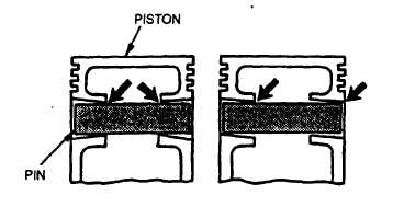
Check taper in piston pin bore by inserting pin from both sides, refer to FIGURE 3-130. If pin enters freely, but
binds in center, bore could be tapered. I bore is not tapered, insert pin to check for bore alignment. Pin should
not click or need to be forced into bore on opposite side.
FIGURE 3-130. Checking Piston Pin Clearance
q.
Check piston pin and piston bore specifications. If either are not within specification, replace pin and/or
piston/liner set.
(1)
Piston large pin OD should be 1.624 to 1.625 inches (41.27 to 41.28 mm).
(2)
Piston pin OD wear tolerance is 0.005 inch (0.13 mm).
(3)
Piston bore for large pin should be 1.625 to 1.626 inches (41.28 to 41.30 mm).
3-191
|
|