TM 9-2920-243-34
CHAPTER 3
REPAIR INSTRUCTIONS
Section I. GENERAL
3-1. Removal and Installation
Before beginning disassembly, wash starter
For instructions covering removal and in-
exterior thoroughly with drycleaning solvent
stallation of the starter, refer to TM 9-2320-211-
Type II (SD-2), Federal Specification P-D-680
20 for LDS-465-1, and LDS-465-1A and MACK
and dry with compressed air (15 psi).
Model ENDT 673 engines, TM 9-2320-209-20 for
3-3. Parts Kit
LD-465-1, LD-465-1C and LDT-465-1C engines,
Standard parts kits should always be used when
and TM 9-2320-230-20 for the LDS-465-2 engine.
repairing or rebuilding starter assembly. Refer to
3-2. Cleaning Before Disassembly
Appendix B for description of parts kits.
Section Il. DISASSEMBLY
3-4. General
a. Disassembly of starter will be performed as
illustrated in the following figures and in-
structions. Sequence of disassembly steps are
shown in alphabetical order on each illustration.
b. All packings and gaskets will be discarded
during disassembly and new parts installed
during assembly.
3-5. Removal of Solenoid Relay
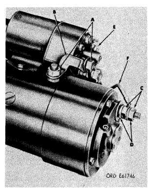
a. Remove in following sequence: two hex nuts
(A, fig. 3-1) and jumper (B); two hex nuts (C) and
lockwashers (D); hex nut (E); and lead assembly
(F).
b. Remove adjusting shaft access plug (fig. 3-
2).
c. Remove two hex-head bolts (A, fig. 3-3)
securing relay assembly (B) to field ring
assembly.
d. Insert shaft adjusting tool (A, fig. 3-4)
through access opening in relay cover. Engage
end of tool with adjusting shaft and turn tool
counterclockwise (B) until relay is free of plunger.
Remove relay assembly (C).
Figure 3-1. Removing or installing jumper and lead assembly.
3-1
|
|


