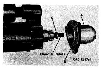
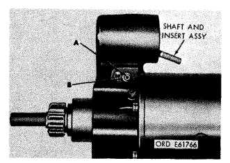
Figure 3-6. Removing or installing pinion housing and
related parts.
b. Disassembly. Remove hex-socket head plug
(A, fig. 3-7) and oil wick (B) from pinion housing.
Remove six seal plugs (C) from housing. Do not
attempt to remove bushing-type bearing since it
should not be replaced unless it fails to meet
inspection requirements (para 3-14b).
3-7. Removal of Shift Housing Assembly
a. Remove hex-socket head screw (A, fig. 3-8)
and flat washer (B).
b. Thread hex-socket head screw (A, fig. 3-9)
into lever shaft (B) and pull shaft from shift
housing. Remove screw and packing (C) from
shaft.
c. Scribe an alinement (A, fig. 3-10) on shaft
housing assembly (D) and field ring. Remove six
hex-socket head screws (B) and
Slide shift housing assembly
position shown in figure 3-11.
lockwashers (C).
(D) forward to
TM 9-2920-243-34
Figure 3-7. Removing or installing pinion housing oil wick.
Figure 3-8. Removing or installing lever shaft retaining screw
and washer.
3-3
|
|


