TM 9-2920-243-34
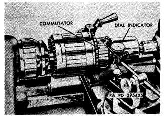
Figure 3-28. Checking armature eccentricity.
h. Commutator End Housing Assembly.
(1) Inspect commutator end head for cracks,
distortion, and burs. Replace if damaged.
(2) Inspect bushing-type bearing for score
marks and wear patterns. Check bearing against
limits specified in repair and rebuild standards
(para 3-31c) and replace if worn beyond limits.
(3) If head bushing-type bearing is removed,
check diameter of bearing bore in commutator end
head against limits specified in repair and rebuild
standards (para 3-31c). Replace head if it is not
within these limits.
i. Shaft and Lever Assembly.
(1) Inspect shaft for wear on shaft or burs in
packing area. Replace shaft if worn or damaged.
Examine nylon insert in threaded portion of shaft
and replace if damaged or worn beyond
usefulness. Check against limits specified in
repair and rebuild standards (para 3-31b) and
replace if parts are beyond these limits.
(2) Inspect lever for wear on slider blocks.
Replace lever if wear exists.
3-15. Repair
a. General. The following subparagraphs cover
only those parts wherein a repair operation will
return damaged part to serviceable condition.
Parts not detailed herein must be replaced when
they fail to pass the required inspection (para 3-
14).
b. Pinion Housing. Smooth minor burs or
damage on mating surfaces of pinion housing
with a fine mill file. If bushing-type bearing did
not meet allowable wear limits, remove it as
shown in figure 3-29 and replace it with a new
bearing. Press new bearing into position. Drill
bushing oil hole using a 21/64-inch diameter drill
and oil wick bore as a pilot. Ream bearing to a
diameter of 0.750 ± 0.001-inch.
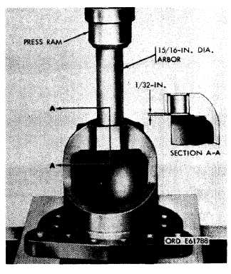
Figure 3-29. Removing or installing bearing in pinion housing.
c. Shift Housing Assembly.
(1) Smooth minor damage such as nicks,
burs, etc., on mating surfaces of housing with a
fine mill file.
(2) If bushing-type bearing did not meet
allowable wear limits, remove the old bearing as
shown in figure 3-30. When installing a new
bearing, reposition housing with opposite side up
from that shown in figure 3-30 and press bearing
in flush with housing bore. Drill bushing oil hole
using a 21/64-inch diameter drill and oil wick bore
as a pilot. Ream bearing to a diameter of 0.875±
0.001-inch.
NOTE
Bearing can be pressed flush more easily
if a 1-inch arbor is used. This will not
allow bearing to be pressed below surface.
3-12
|
|