TM 9-2920-243-34
Figure 3-30. Removing or installing bearing in shift housing.
d. Commutator End Housing Assembly.
(1) Smooth minor damage such as nicks,
burs, etc., on mating surface of housing with a
fine mill file.
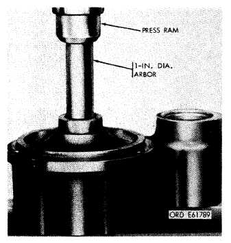
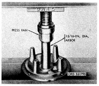
(2) If bushing-type bearing did not meet
allowable wear limits, remove old bearing as
shown in figure 3-31. Install a new bearing in the
same manner. It should be pressed in so that it is
flush with housing bore. Drill bushing oil hole
using a 21/64-inch diameter drill and oil wick bore
as a pilot. Ream bearing to a diameter of 0.730±
0.001-inch.
NOTE
Bearing can be pressed flush more easily
if a 15/16-inch arbor is used. This will not
allow bearing to be pressed below surface.
Figure 3-31. Removing or installing bearing in commutator
end housing.
e. Armature.
(1) Resurfacing. Sharpen lathe cutting tool to
dimensions given in figure 3-32. For commutator
turning, lathe cutting tool must be extremely
sharp. After grinding, hone tool with a fine hard
stone to insure a smooth cut during turning
operation.
Position tool with respect to commutator as
shown in figure 3-33. Resurface commutator at
800 rpm taking only light cuts each time. No more
than 0.005-inch should be removed during any
one cut and the final cut should not be more than
0.002-inch. After resurfacing, check commutator
against limits specified in repair and rebuild
standards (para 3-31) and replace it if it falls
below these limits.
NOTE
When a cut is started, it should be carried
across entire surface without stopping.
3-13
|
|