| Tweet |

Custom Search
|
|

|
||
 TM 9-8000
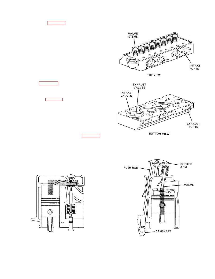
(2) L-Head (Fig. 2-35). The intake and the
exhaust valves were both located on the same side of
the piston and cylinder. The L-head engine was a much
simpler design than the T-head because it required only
one camshaft. The L-head engine got its name from the
imaginary letter formed by the piston and the valve
heads.
b. Valves in the Cylinder Head. These engines
come in two groups.
The first group have their
camshafts located in their cylinder blocks.
These
engines are known as the overhead valve (ohv) engines.
The second group have their camshafts located in their
cylinder heads. These engines are known as the
overhead camshaft (ohc) engines. A typical ohv cylinder
head is shown in figure 2-36. The configurations of valve
trains for engines with the valves in the head are as
follows.
(1) I-Head (Fig. 2-37). This configuration has
its camshaft located in the cylinder block. The camshaft
operates the valves through the lifter, push rod, and
rocker arm. The I-head gets its name from the letter
formed by the piston and the valve. Although this
configuration is the most popular for current gasoline and
diesel engines, it Is rapidly being superseded by
overhead camshaft configurations in passenger cars.
(2) Single Overhead Camshaft (Fig. 2-38).
Figure 2-36. Typical Overhead Valve Cylinder Head
This configuration has its camshaft located in the
cylinder head. When the single overhead camshaft
arms as shown in view B. The single overhead camshaft
configuration is used, the intake and the exhaust valves
configuration is rapidly becoming the most popular one
are both operated from a common camshaft. The valve
for passenger car gasoline engines.
train may be arranged to operate the valves directly
through the lifters as shown in view A. The valve train
also may be arranged to operate the valves through
rocker
Figure 2-35. L-Head Engine
Figure 2-37. I-Head Engine
TA233332
2-24
|
||
 |
||