| Tweet |

Custom Search
|
|

|
||
 TM 9-8000
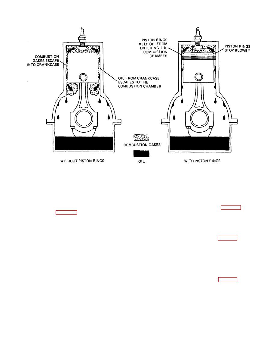
Figure 3-17. Purpose of Piston Rings.
c. Configurations. Piston rings are arranged
(3)They provide a solid bridge to conduct
the heat from the piston to the cylinder wall. About
on the pistons in three basic configurations. They
one-third of the heat absorbed by the piston
are:
passes to the cylinder wall through the piston
rings.
(1) The three-ring piston (A, fig. 3-19)
b. Description (Fig. 3-18). Piston rings are
that has two compression rings from the top,
secured on the pistons by fitting Into grooves.
followed by one oil control ring. This is the most
They are split to allow for installation and expan-
common piston ring configuration.
sion, and they exert an outward pressure on the
cylinder wall when installed. They fit into grooves
that are cut into the piston, and are allowed to float
(2) The four-ring piston (B, fig. 3-19) that
freely in these grooves. A properly formed piston
has three compression rings from the top,
ring, working in a cylinder that is within limits for
followed by one oil control ring. This configura-
tion is common in diesel engines because they are
roundness and size, will exert an even pressure
and a solid contact with the cylinder wall around its
more prone to blowby. This is due to the much
entire circumference. There are two basic clas-
higher pressures generated during the power
sifications of piston rings.
stroke.
(1) The Compression Ring. The compres-
sion ring seals the force of the exploding mixture
has two compression rings from the top, followed
into the combustion chamber.
by two oil control rings. The bottom oil control ring
may be located above or below the piston pin. This
(2) The Oil Control Ring. The oil control
is not a very common configuration in current
ring keeps the engine's lubricating oil from get-
engine design.
ting Into the combustion chamber.
TA233361
3-11
|
||
 |
||