| Tweet |

Custom Search
|
|

|
||
 TM 9-8000
almost at the end of the compression stroke, and the fuel
described in paragraph 5-16, uses a pump that sends
is being pressurized by the plunger.
measured charges of fuel to each injector at a properly
timed interval. The difference in the PSB system is that
(3) Injection (C, Fig. 5-18). The plunger is almost
the charges of fuel are sent directly from the pump at the
high pressure that is necessary for injection.
This
all the way down, the fuel is injected out the eight
eliminates the need for unit-type injectors and the
orifices, and the engine is on the very end of the
associated linkage and camshafts, making the system
compression stroke.
less cumbersome. The injectors are of the same basic
design as the ones used in the multiple unit injection
system (para 5-14). The nozzles usually are of the hole
way down, injection is finished, and the fuel is flowing
type (para 5-14).
into the injector, around the lower annular groove, up a
drilled passageway in the barrel, around the upper
b. The PSB Injector Pump.
The PSB injection
annular groove, and out through the fuel drain.
The
pump (Fig. 5-20) is compact and self-contained,
cylinder is on the power stroke.
During the exhaust
housing all components of the injectors. Operation is
stroke, the plunger moves up and waits to begin the
shown in figure 5-21.
cycle all over again.
(1) The PSB pump contains a plunger-type
5-19.
PSB Distributor lnjection System.
pump that creates the high-pressure fuel charges for the
injectors. The pump is driven by a camshaft
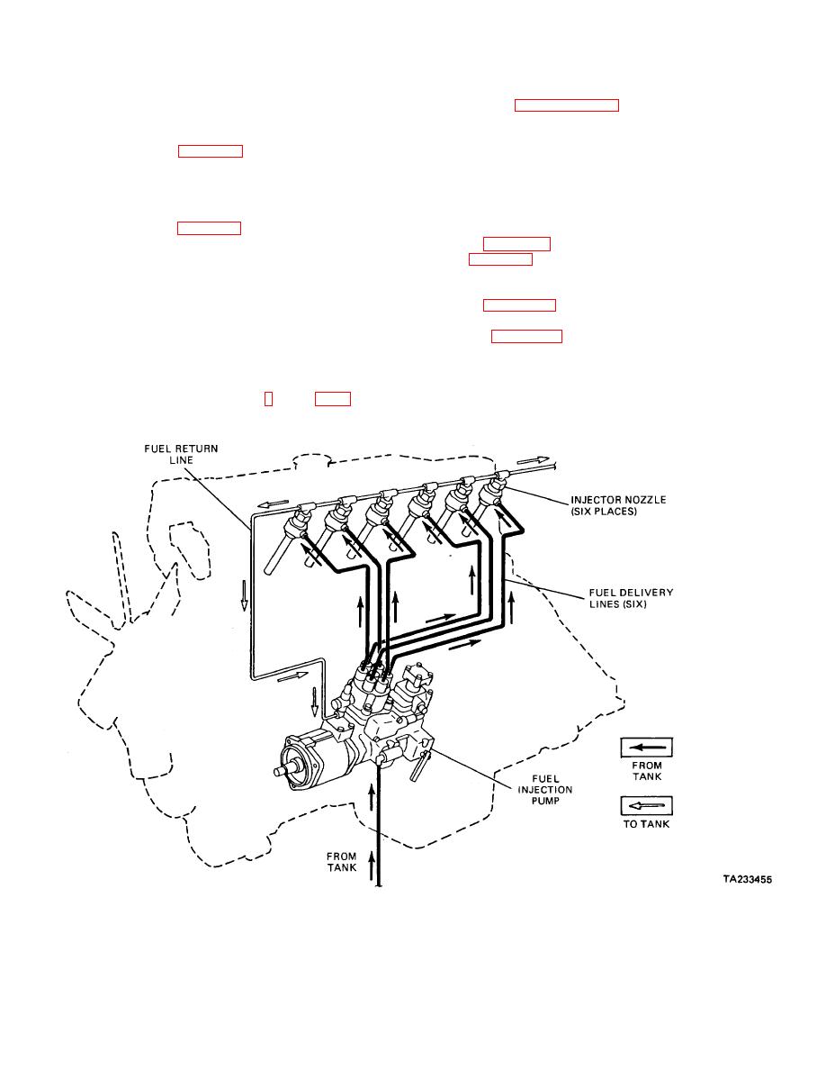
a. Overall System Operation (Fig.
5-19). The
PSB distributor system, like the distributor system
Figure 5-19. PSB Distributor Injection System.
5-25
|
||
 |
||