
| Tweet |

Custom Search
|
|

|
||
 TM 9-8000
bore and keyway. The hub Is secured to the camshaft
both the weight and spider assembly and the timing
extension by a woodruff key, nut, and setscrew. The
device hub.
Correct assembly of the spline train is
hub usually Is counterbored to receive the timing device
ensured by a wide land on both the hub and weight and
springs. The springs oppose the flyweight forces of the
the spider assembly. The sliding gear has a missing
weight and spider assembly.
tooth on each set of Internal splines to receive the wide
lands. Three arms extend from the outer surface of the
c, The weight and spider assembly has external
sliding gear to provide seats for the three timing device
right-hand helical splines to mesh with the Internal helical
springs. The force on these springs Is controlled by a
splines of the sliding gear. The spllned end is machined
sliding gear spacer.
to receive the end play spacer. Three flyweights are
pinned to a flange adjacent to the spilnes. The weight
5-30.
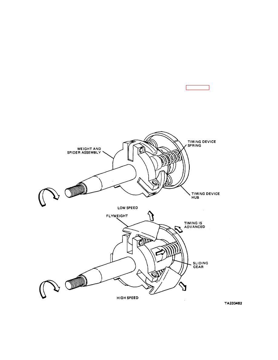
Operation (Fig. 5-26).
and spider thrust plate located between the flange and
the timing device housing carries the back thrust of the
a. As the engine rotates the weight and spider
flyweights and prevents housing wear.
assembly, centrifugal force opens the flyweights from
their collapsed position against the force of the three
d. The sliding gear has Internal left-hand helical
timing device springs.
splines at one end and Internal right-hand helical splines
at the other end and meshes with the external splines of
Figure 5-26. Timing Device Operation.
5-34
|
||
|
||


