
| Tweet |

Custom Search
|
|

|
||
 TM 9-8000
generator speeds can be two to four times engine rpm.
13-5. Field Intensity. The magnetic lines of force that
are created by the generator field are critical to the
generator's output. The more lines of force that there
are for the armature to cut, the more output the
generator will produce.
Generator field coils are
designed to produce the most intense field that is
possible. The key factors that affect field intensity are:
a. The number of wire turns in the coil.
b. The ratio of the coil's length to its width.
c. The type of material used in the core.
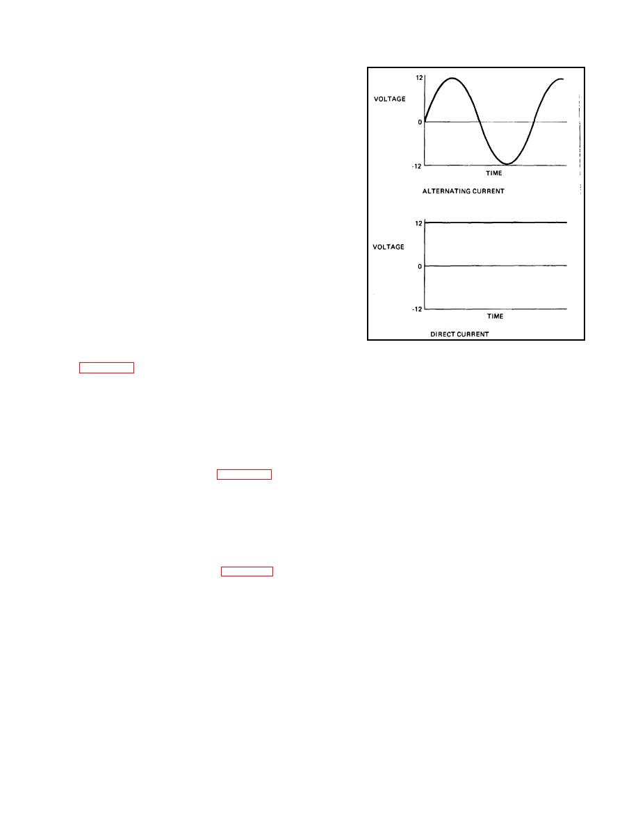
13-6. AC and DC Current Flow.
a. General. There are two basic forms of electrical
current flow: Direct current (dc) and alternating
current(ac).
b. Alternating Current. Alternating current forces
electrons from one terminal to the other and then back
again (the direction of current flow alternates). A graph
Figure 13-3. AC and DC Flow.
of the voltage versus time for alternating current is
shown in figure 13-3. It can be seen that the value of the
produces dc flow, must also have a dc flow, because ac
voltage rises in the positive direction, reaches a peak,
and dc flow are incompatible in the same circuit. To
falls in the negative direction, reaches a negative peak,
correct this problem, the generator output therefore must
and then rises to zero. This is a constantly repeating
be changed to dc through a process called rectification.
cycle. Generators normally produce alternating current.
By its design, a dc generator is self-rectifying, but an ac
generator must have its output rectified electronically.
c. Direct Current. Direct current flow forces electrons
The processes of rectification are respectively covered in
from the negative terminal to the positive terminal
their related sections.
(current flow is always in one direction or direct). Direct
current voltage versus time is shown in figure 13-3.
d. Compatibility. An automotive electrical system, due
to the need for a storage battery that
Section II. DC GENERATOR PRINCIPLES
This is called shunt-field winding.
The shunt-field
13-7. Field Winding Configurations (Fig. 13-4). The
winding usually is connected only at one end to the
purpose of the field windings is to create the lines of
brushes. The other end of the field winding then is made
force electromagnetically that induce a current flow in the
to pass through a voltage regulation circuit (para 13-13).
armature. The field winding usually is connected in
In this manner, the output of the generator is controlled.
parallel with the armature winding (that is, across the
Depending on the
brushes).
TA233543
13-3
|
||
|
||


