
| Tweet |

Custom Search
|
|

|
||
 TM 9-8000
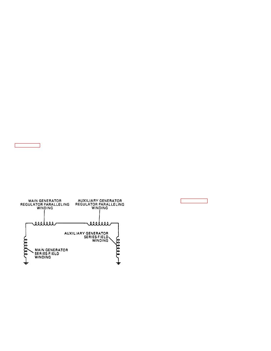
series with the paralleling windings in the two voltage
auxiliary generator. Under these conditions, there will
regulators and to the two series-field windings in the two
be a greater voltage across the main generator series-
generators. Whenever a generator begins to charge, the
field winding. This means that current will flow from this
armature on the pilot relay moves from the upper to the
winding, through the paralleling windings, and the
lower position, opening the upper and closing the lower
auxiliary generator series-field winding. The current flow
contacts. When the upper contacts are closed (meaning
through the paralleling windings in the regulators helps
that the generator is not charging), the paralleling relay
the regulating winding in one regulator and opposes the
winding is shorted through them and no paralleling relay
regulating winding in the other. it helps in the main
action can take place. But when the pilot relay opens
generator regulator; this means that the spring pressure
these upper contacts and closes the lower contacts, the
on the carbon-pile armature is lightened further so that
winding of the paralleling relay becomes connected
the carbon-pile resistance increases, cutting down the
across the generator. Now, generator voltage can
main generator output.
On the other hand, the
energize the winding and cause the paralleling relay to
paralleling winding in the auxiliary generator regulator
close its contacts. Only one paralleling relay will be
opposes the regulating winding. This means that the
actuated if only one generator is operating. This means
spring pressure on the carbon-pile armature is
that no paralleling can take place. But when both
increased. Carbon-pile resistance is reduced and the
generators are operating so that both paralleling relays
auxiliary generator output goes up.
are in action, then the contacts of the relays, the
(3) Paralleling. With paralleling, if one generator tries
paralleling windings in the regulators, and the series-field
windings in the generator are all in series.
to produce more output than the other, its output is cut
(2) Operation. When all are in series, current will flow
down immediately while the output of the low generator
in the circuit if one generator is putting out more current
is increased. The action is entirely automatic once the
than the other. To understand how this might be, refer to
system has been adjusted correctly. In order to achieve
adjustment, the voltages of the two carbon-pile
series-field windings and the regular paralleling windings
regulators must first be set, then the voltages perfectly
connected in series. The paralleling relay contacts are
balanced by means of the no-load voltage-adjusting
not shown here because they are closed and are
potentiometer, or pot.
Finally, the two paralleling
therefore a part of the circuit. Suppose that the main
rheostats must be adjusted. All these adjustments must
generator is putting out more current than the auxiliary
be made by authorized personnel and according to
generator. This means that more current flows through
instructions supplied in the applicable technical manual.
the series-field winding of the main generator than
g. Regulators. The carbon-pile regulators, one for
through the series-field winding of the
each generator, operate on generator voltage (para 13-
16). A simplified sketch of one carbon-pile regulator
circuit is shown in figure 13-20 (paralleling winding not
shown). Some special features of this circuit will be of
interest.
The carbon pile is connected between the insulated
generator brush and the generator shunt field. The
regulator winding is connected across the generator
brushes so that full generator voltage is imposed on it. It
therefore regulates on generator voltage as explained in
paragraph 13-16. There is a voltage-adjusting rheostat
connected in series with the winding so that voltage
adjustment can be made. In addition, the circuit goes to
ground through an adjustable resistor called a
potentiometer.
The potentiometer permits accurate
balancing of the two voltage regulator settings.
TA233560
Figure 13-19. Paralleling Relays.
13-21
|
||
|
||


