| Tweet |

Custom Search
|
|

|
||
 TM 9-8000
(6) Clutch Springs. The clutch springs
made of steel with no facing. They usually have teeth
cut into their outer circumference to positively key them
ensure rapid release of the clutch when hydraulic
inside of a clutch drum or to the inside of the
pressure to the clutch piston is released. The clutch
transmission case. By alternately stacking the disks and
springs may be in the form of several coil springs equally
plates, they are locked together or released by simply
spaced around the piston or one large coil spring that fits
squeezing them.
in the center of the clutch drum. Some models use a
diaphragm-type
(2) Clutch Drum and Hub. The clutch drum
(Belleville) clutch spring.
holds the stack of disks and plates, and usually is
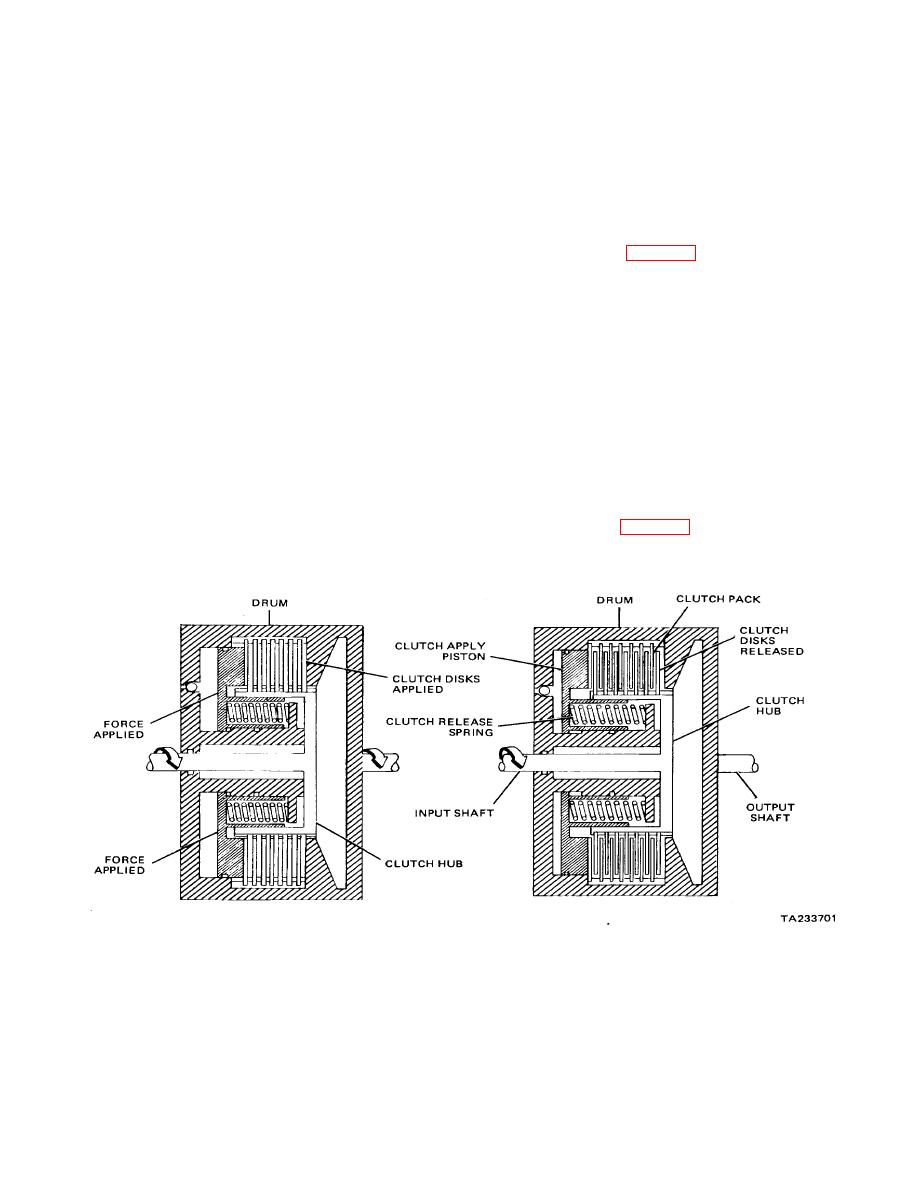
c. Operation(Fig. 23-3).
attached to the planetary gearset element that is being
driven. The clutch hub usually attaches to the driving
(1) Released. When the clutch is released,
member and fits inside of the clutch disks and plates.
there is no hydraulic pressure on the clutch piston and
(3) Pressure Plate. The pressure plates
the clutch disks and plates are free to rotate within each
are thick clutch plates that are placed on either end of
other. The result is that the clutch hub rotates freely and
the stack. Their purpose is to distribute the application
does not drive the clutch drum.
pressure equally on the surfaces of the clutch disks and
(2) Applied. When the clutch is applied,
plates.
hydraulic pressure is applied to the clutch piston which,
(4) Clutch Piston. The clutch piston uses
in turn, applies pressure to the clutch disks and plates,
hydraulic pressure to apply the clutch. Hydraulic
causing them to lock together. The result is that the
pressure usually is supplied to the clutch piston through
clutch hub drives the clutch drum through the clutch.
the center of the rotating member.
23-6.
Brake Band.
(5) Clutch Piston Seals. The clutch piston
seals serve to prevent the leakage of hydraulic pressure
a. General (Fig. 23-4). The brake band is used
around the inner and the outer circumferences of clutch
to lock a planetary gearset element to the
piston.
Figure 23-3. Multiple-Disk Clutch Operation.
23-3
|
||
 |
||