
| Tweet |

Custom Search
|
|

|
||
 TM 9-8000
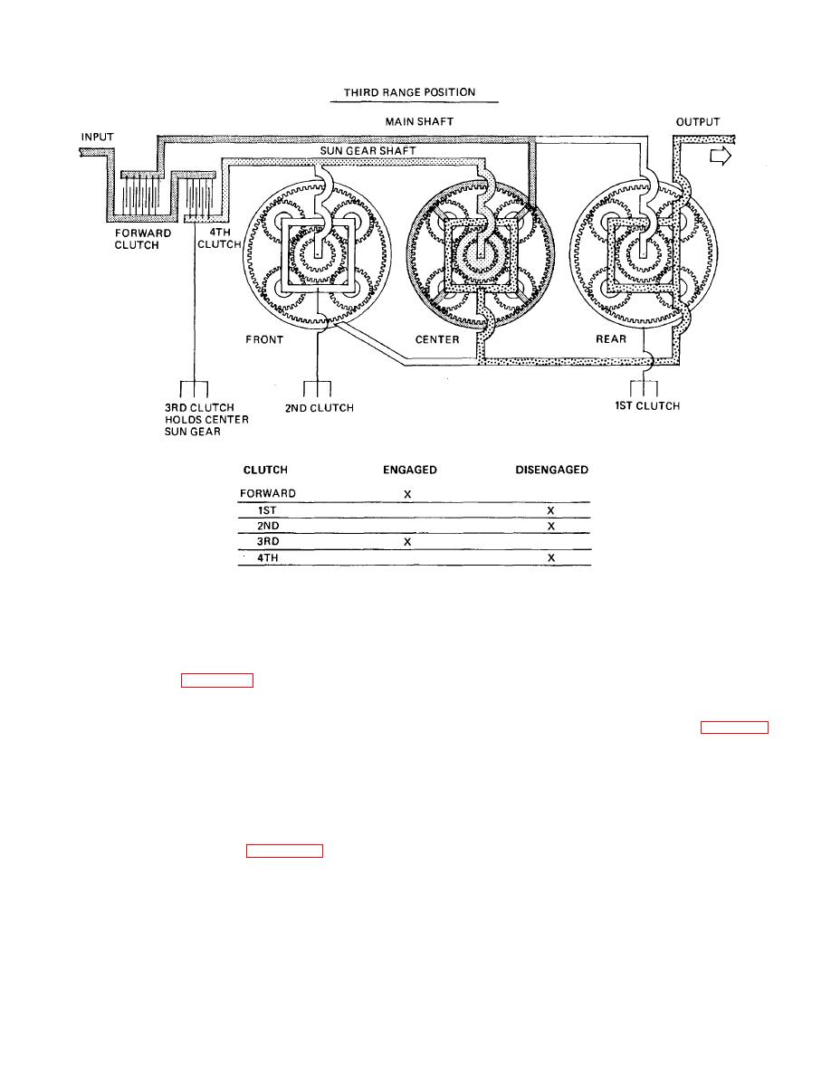
Figure 25-7. Power Flow through X1100 Transmission in Third Range
connected to the hanging ring by a pin. The pin transmits
a position that interrupts the control pressure circuit
the partial rotation of the hanging ring to the servo
actuating the control pistons. This action overrides steer
sleeve.
control to the extent of reducing steer to the degree
possible under overload conditions.
d. Servo Valve (Fig. 25-12). Centered within the
servo sleeve is the manually controlled servo valve
25-8. Final Drive.
which, when rotated, directs control pressure to either of
the two control pistons. Clockwise rotation of the servo
a. General. The final drive assembly (fig. 25-15) is
valve from its normally centered position gives steer in
a self-contained, heavy-duty planetary gear speed-
one direction; counterclockwise rotation gives steer in the
reduction unit. The input spline is integral with the
other direction. The control pistons have no pressure
planetary sun gear. The planetary ring gear is bolted to
acting upon them when no steer is applied. Their oil lines
the final drive housing and, therefore, is stationary. The
are open to exhaust through the servo
planetary carrier, with planet pinion gears, is splined to
valve.
the output shaft. The final drive unit is identical for both
left and right transmission outputs. The dry weight of
e. Stroke Limiter Valve (Fig. 25-12). A stroke
each final drive is approximately 940 lb.
limiter valve is provided in the control circuit. Under
normal condition the valve remains in the position shown.
The oil supply is contained in the bottom of the housing
Under conditions that overload the hydrostatic pump
and provides both cooling and lubrication for the unit.
(approximately 5000 psi), the excessive output pressure
Lubrication is obtained by the splash
pushes the valve to
TA233748
25-7
|
||
|
||


