| Tweet |

Custom Search
|
|

|
||
 TM 9-8000
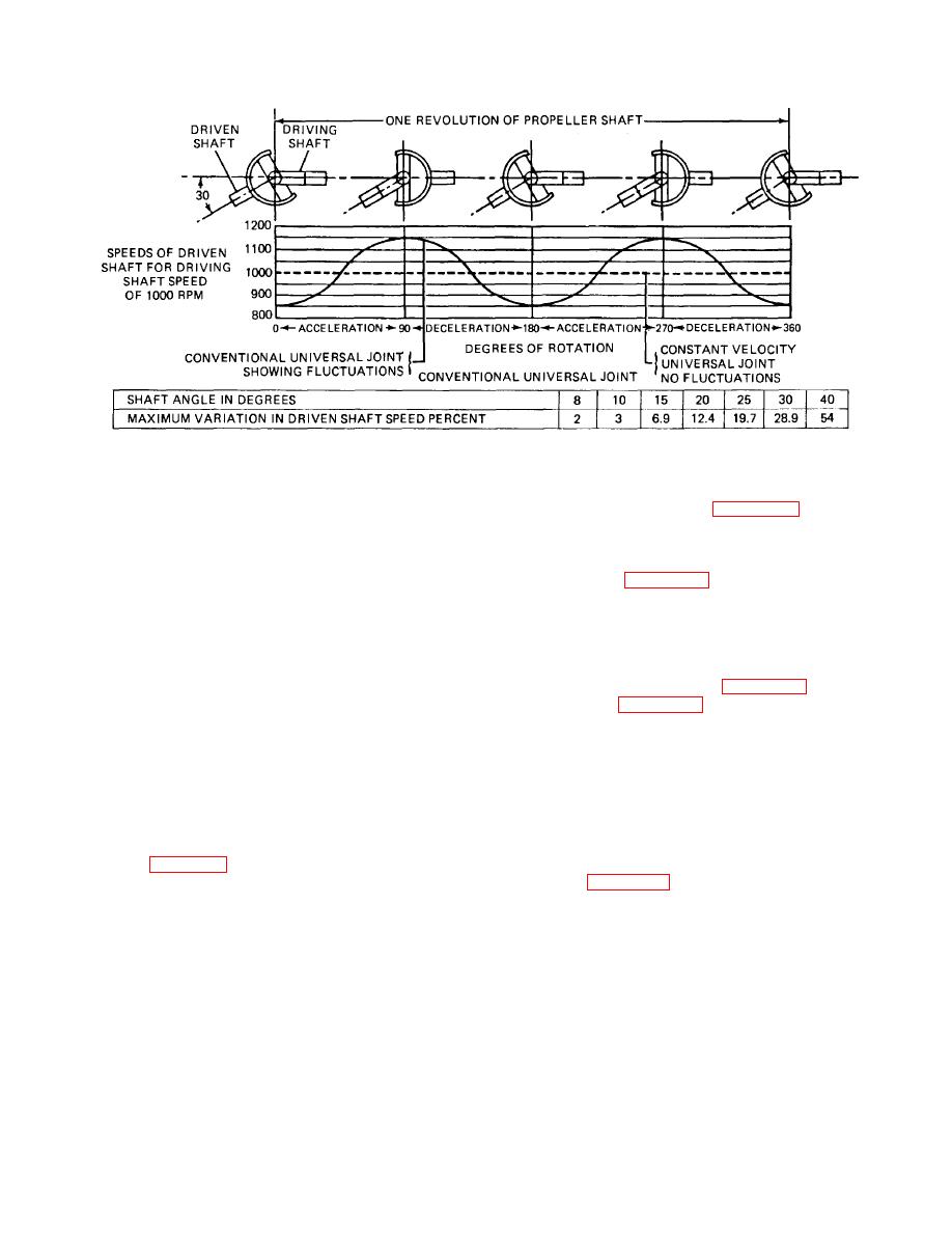
Figure 28-3. Speed Fluctuations Caused by Conventional Universal Joints.
are employed, the second joint is used to compensate
which are shown in A and B, figure 28-4. The different
for the speed fluctuations caused by the first. In order to
universal joints of this type vary from each other mainly
accomplish this, the angle between the transmission
in the manner in which the journal is attached to the
shaft and the propeller shaft must be the same as the
driving and driven yokes. For example, in the universal
angle between the propeller shaft and the final drive of
joint shown in A, figure 28-4, the journal is assembled in
the rear axle. Another requirement is that the two yokes
the shaft and slip yokes, the bearing assemblies inserted
of the universal joint that are attached to the propeller
from the outside and secured by spring bearing retainers
shaft be in the same plane. If the yokes of the joints
inside the yokes. The bearings on the transverse ends
attached to the propeller shaft are in the same plane, the
of the journal are clamped to the flange yokes and
driving yoke of the first joint will be at an angle of 90
secured from outward movement by bearing retainers.
degrees with the driving yoke of the second. The two
The universal joint shown in A, figure 28-4, differs from
yokes attached to the propeller shaft act as the driven
that shown in B, figure 28-4, in the manner in which the
yoke of the first joint and the driving yoke of the second
journal is attached to the flange yoke. In this universal
joint, respectively. With this arrangement, the first joint is
joint, the bearing assembly is contained in bearing
producing its maximum fluctuation at the same time the
blocks. The blocks are mounted against the flange
second joint is producing its minimum fluctuation. This
yokes and secured with bolts extending longitudinally
results in a nonvarying wheel speed for a given engine
through the yokes.
speed, even though the speed of the shaft between the
b. Ball and Trunnion. Two universal joints of the
joints is changing constantly.
ball-and-trunnion type are used in an application, one on
each end of the propeller shaft. This type of joint is
shown in C, figure 28-4. There is a trunnion pin through
bearings are included at the four points where the journal
the end of the propeller shaft. The pin is fitted with balls
is attached to the yokes. In addition, one of the yokes
that ride in grooves in the flanged body. The balls are
usually incorporates a splined slip joint. In one type of
assembled on bearings so they can rotate with little
universal joint (the ball-and-trunnion type), the universal
friction. Compensated springs at each end of
joint itself incorporates a feature that permits variations in
TA233771
length of the propeller shaft.
a. Journal-Type Universal Joint. There are
several variations of this type of universal joint, two of
28-3
|
||
 |
||