| Tweet |

Custom Search
|
|

|
||
 TM 9-8000
but a hollow shaft is much stronger than a solid shaft of
shaft.
the same weight.
b. Construction. A slip joint consists of a male and
female spline, a grease seal, and a lubrication fitting.
28-2.
Slip Joints(Fig. 28-1).
The male spline is an integral part of the propeller shaft
and the female portion is fixed to the universal joint
a. Purpose. Because flexing of the springs causes
directly behind the transmission or transfer case. As the
the axle housing to move forward and backward, some
axle housing moves forward and backward, the slip joint
provision must be made to allow the propeller shaft to
gives freedom of movement in a horizontal direction and
contract and expand. A device known as a slip joint
yet is capable of transmitting rotary motion.
provides the necessary telescopic action for the propeller
Section II. CONVENTIONAL UNIVERSAL JOINTS
the speed, twice during each revolution. The extent of
such fluctuation depends on the amount of angularity,
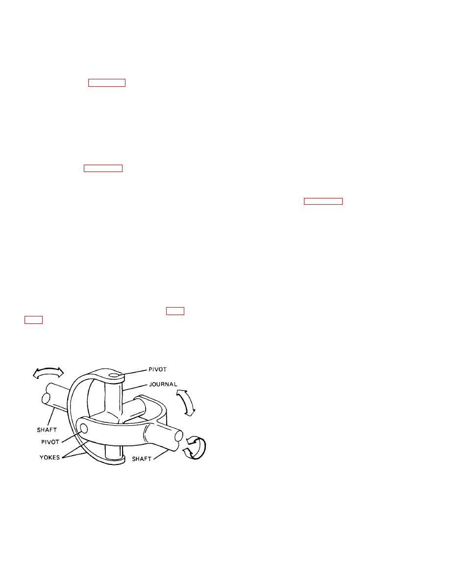
flexible coupling between two shafts that permits one
roughly about 7 percent for an angle of 15 degrees, and
shaft to drive another at an angle to it. It is flexible in the
about 30 percent for an angle of 30 degrees. This fact is
sense that it will permit power to be transmitted while the
shown graphically in figure 28-3, where the variations of
angle between the shaft is being varied continually. A
the angular velocity during one revolution of a shaft
simple universal joint is composed of three fundamental
driven through a conventional universal joint are plotted.
units consisting of one journal and two yokes. The two
The driving shaft is running at a constant velocity of
yokes are set at right angles to each other, and their
1,000 rpm, and the angle between the shafts is 30
open ends are joined by the journal. This construction
degrees. Sketches of the universal joint positions at the
permits each yoke to pivot on the axis of the journal and
minimum and maximum velocity fluctuation points are
also permits the transmission of the rotary motion from
placed above the corresponding portions of the curve to
one yoke to the other. As a result, the universal joint can
enable the reader to correlate the curve with the action of
transmit the power from the engine through the shaft to
the universal joint yoke and journal.
the drive axle, even though the engine is mounted rigidly
in the frame at a higher level than the axle, which is
a. In a quarter of a revolution, the speed of the
constantly moving up and down in relation to the frame.
driven shaft varies from a minimum of 866 to a
maximum of 1,155 rpm. The speed of the driven shaft
28-4. Characteristics of Operation (Fig.
equals that of the driving shaft at four points during the
revolution; that is, 45, 135, 225, and 315 degrees, where
that it causes a driven shaft to rotate at a variable speed
the curve intersects the constant velocity (dotted) line.
in respect to the driving shaft. It has been found that
The extent of each fluctuation depends on the size of the
there is a cyclic variation, in the form of an acceleration
angle between the shafts; the greater the angle, the
and a deceleration of
greater the variation in the speed of the two shafts.
b. This variation of velocity cannot be eliminated
with a simple universal joint, but its effect can be
minimized by using two universal joints, one at each end
of the shaft. If only one joint is used between the
transmission and the rear axle, the acceleration and
deceleration caused by the joint is resisted on one end
by the engine and on the other end by the inertia of the
vehicle. The combined action of these two forces
produces great stress on all parts of the power train and,
in addition, results in a nonuniform force being applied to
the wheels. When two universal joints
TA233770
Figure 28-2. Typical Universal Joint.
28-2
|
||
 |
||