
| Tweet |

Custom Search
|
|

|
||
 TM 9-8000
Section IV. CONTROLLED DIFFERENTIAL
29-11. Purpose. The controlled differential is used in
tracked vehicles for:
vehicle is moving straight ahead, the entire differential
assembly turns as a unit and transmits equal power and
(a) Transmitting engine torque to the tracks.
speed to each track through the final drive. When the
left brake band is applied to the brakedrum, the left
(b) Steering of the vehicle through the controlled
compensating gear is retarded and rotates slower than
use of side-to-side braking.
the differential carrier, while the right compensating gear
is speeded up and rotates faster than the differential
carrier. As each compensating shaft is splined to each
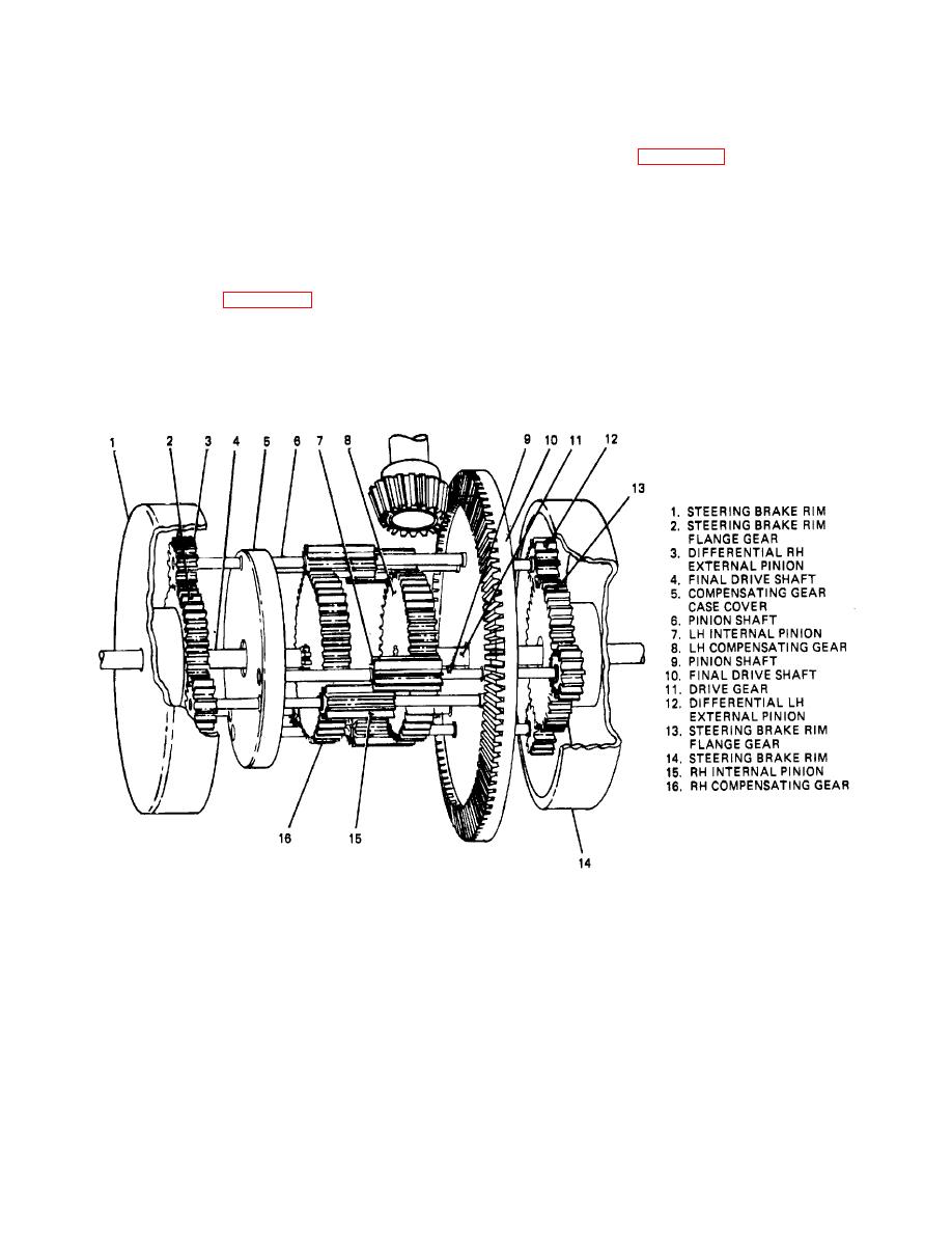
29-12. Construction (Fig. 29-21 and 29-22). The
compensating gear, the final analysis will result in the left
controlled
differential is, in reality, two different
track revolving slower than the right track, causing the
assemblies having left and right units joined by the
vehicle to turn to the left. Exactly the reverse procedure
differential carrier. Each side consists of a brakedrum, a
takes place if the right brake is applied.
sun gear, three external pinions, three internal pinions,
and one compensating gear.
TA233797
Figure 29-21. Controlled Differential.
29-22
|
||
|
||


