
| Tweet |

Custom Search
|
|

|
||
 TM 9-8000
energy of the road shock, rather than just one end.
raised or lowered half this amount. In this manner, bogie
Thus, the effect of road shocks is cut in half. When only
axles reduce by half the impact or shock not only to the
one axle is deflected up or down from its normal loaded
vehicle, but also to the road.
position, the trunnion axle and the vehicle frame are
Section V. AIR-OVER-HYDRAULIC SUSPENSION
the intake valve is opened by the linkage, allowing
30-13. Purpose. The air-over-hydraulic suspension
pressure to increase in the shock absorber. This, in turn,
system is designed to keep the body level under different
raises the vehicle to its normal position. As soon as the
loading conditions.
When the vehicle weight is
vehicle is level, the intake valve closes and a steady
increased, either by adding cargo or passengers, the
pressure is maintained in the shocks. When weight is
body will become lower to the ground. The leveling
removed from the vehicle, the linkage opens the exhaust
system then will sense a low condition and allow
valve and pressure is released in the shocks, restoring
pressure to increase in the special shock absorbers,
the vehicle to a normal riding position. The linkage also
raising the body with respect to the ground. When the
is dampened through the use of a fluid to prevent the
weight is removed, the system will allow air pressure to
control valve from reacting to bumps and changes in
bleed from the air shock absorbers, restoring the vehicle
road conditions.
to its normal riding height.
30-14. Components of Air-Over-Hydraulic
Suspension.
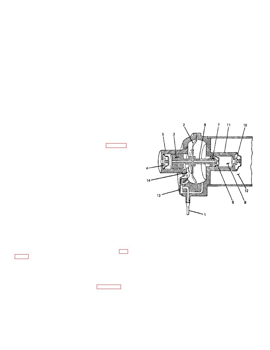
a. Air Compressor. The air compressor (fig. 30-
17) is commonly a vacuum-operated two-stage unit
requiring no lubrication. The sliding distributor valve
directs intake manifold vacuum alternately to the right or
left side of the diaphragm, moving it from side to side.
When the diaphragm, which is connected to a double
piston, moves to the right, it allows air to enter the first
stage chamber. At the end of the stroke, the check valve
on that chamber closes, and the distributor valve diverts
the vacuum to the opposite side of the diaphragm. As
the piston then moves to the left, the air in the first stage
moves through the air passage in the center of the piston
to the second stage chamber. At the end of that stroke,
the check valve on the air passage closes and, as the
piston moves to the right again, the check valve on the
1. VACUUM LINE
8. AIR PASSAGE
second stage cylinder opens, allowing the compressed
2. DIAPHRAGM
9. SECOND-STAGE
air to enter the air reservoir tank. As pressure in the
CYLINDER
reservoir tank builds up to a predetermined amount, it
3. PISTON
10. CHECK VALVE
puts an equal force on the second stage piston and the
4. CHECK VALVE
11. SECOND-STAGE
pumping action stops.
HOUSING
5. FIRST-STAGE HOUSING
12. AIR RESERVOIR
b. Pressure Regulator Valve. This component (fig.
TANK
6. CHECK VALVE
13. SLIDING
valve to a predetermined amount, regardless of the
DISTRIBUTOR
pressure in the reservoir. The valve is nonadjustable
7. SECOND-STAGE END
VALVE
and must be replaced if proper pressure is not
OF PISTON
14. ARM
maintained.
Figure
30-17. Air
TA233810
c. Height Control Valve. This valve (fig. 30-19) is
attached to the frame of the vehicle, and linkage is used
to attach the valve to the suspension system. When the
frame moves downward because of additional weight,
30-12
|
||
|
||


