
| Tweet |

Custom Search
|
|

|
||
 TM 9-8000
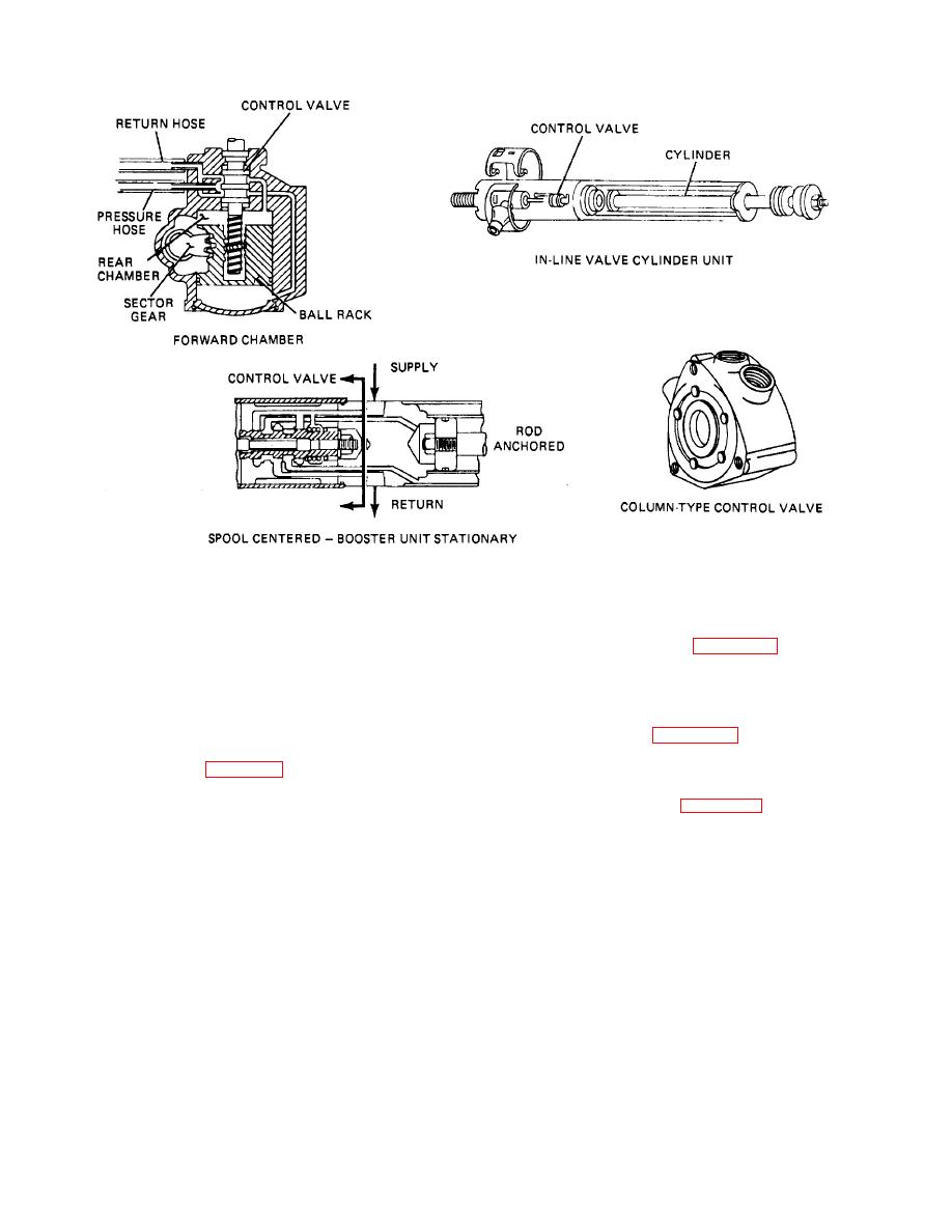
Figure 33-13. Control Valve
valve is centered by springs or hydraulic pressure or a
33-12. Configurations.
combination of both. This allows the oil to flow through
the valve and back to the reservoir. This condition allows
a. Linkage Type (A, Fig. 33-16). In the linkage
the steering system to maintain its position.
configuration, the control valve and power cylinder may
be separate parts and mounted on different parts of the
b. Left and Right Turns. As the driver attempts to
linkage.
turn the steering wheel to make a left or right turn, the
power steering system is activated. The spool is moved
b. Integral (B, Fig. 33-16). The integral system
off its center position and is forced to the left or right end
incorporates the control valve and power assist into the
of the control valve (fig. 33-13). This opens the proper
steering gear as a unit.
passageways for the pressurized oil. It is directed to the
proper side of the piston in the steering box or end of the
c. Semi-Integral (C, Fig. 33-16). The control valve
hydraulic cylinder if linkage-type power steering is
on the semi-integral system is mounted to the steering
employed. The return port is also opened and the fluid
gear and a separate hydraulic cylinder is mounted to the
that is being displaced by the piston in the cylinder is
linkage.
allowed to return to the reservoir.
TA233843
33-10
|
||
|
||


