
| Tweet |

Custom Search
|
|

|
||
 TM 9-8000
CHAPTER 36
ACCESSORIES
Section I. POWER TAKEOFF
shaft, controlled by a lever in the driver's cab, slides the
36-1. Purpose. A power takeoff Is an attachment for
gear in and out of mesh with the countershaft gear.
connecting the engine to power-driven auxiliary
Since it is driven by the countershaft, the power takeoff
machinery when its use Is required. It is attached to the
shaft rotates in the same direction as the engine
transmission, auxiliary transmission, or transfer case. A
crankshaft.
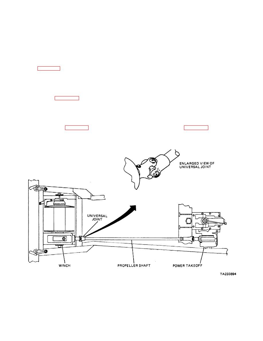
power takeoff installed at the left side of a transmission
Is shown in figure 36-1. It is used to drive a winch,
36-3. Main Transmission Power Takeoffs.
located at the front of the truck, through a universal joint
and propeller shaft.
Transmission power takeoffs are available in several
different designs: a single-speed, twogear model in
which the rotation of the power takeoff shaft is opposite
36-2. Construction. The simplest type of
to that of the engine; a model having a single speed
transmission power takeoff is the single-gear, single-
forward and reverse; and a model having two speeds
speed type shown in figures 36-2 and 36-3. This unit is
forward and one reverse. Several different mountings
bolted over an opening provided for the purpose at the
also are available.
side of the transmission case. This opening is closed by
a cover plate when no power takeoff is used. The
38-4. Auxiliary Transmission Power Takeoffs. The
opening in the transmission case and the power takeoff
gear meshes with a gear on the transmission
same types of power takeoffs also are applied to
countershaft. As shown in figure 36-2, the gear slides on
auxiliary transmissions. Figure 36-4 shows a winch
the splined main shaft, off which the power is taken. The
driven off an auxiliary transmission.
shifter
Figure 36-1. Winch and Power takeoff Installation.
36-1
|
||
|
||


