| Tweet |

Custom Search
|
|

|
||
 TM 9-8000
Section II. SYSTEM COMPONENTS
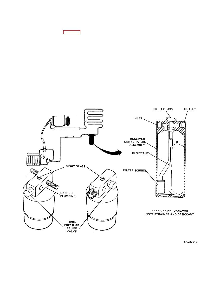
c. Relief Valve. Some systems utilize a relief
known as a filter-drier or accumulator-drier, is a
valve mounted near the top of the receiver. This valve is
cylindrical-shaped metal tank. The tank is hollow with an
designed to open when system pressure exceeds
inlet to the top of the hollow cylinder. The outlet port has
approximately 450 to 500 psi. As the relief valve opens,
a tube attached to it that extends to the bottom of the
it vents refrigerant into the atmosphere. As soon as
receiver. This tube assures that only liquid refrigerant
excess pressure is released, the valve closes again so
will exit the receiver, because any gas entering will tend
the system will not be evacuated completely.
to float above the liquid.
d. Sight Glass. A sight glass is a small, round,
a. Filter. The filter is mounted inside the
glass-covered hole, sometimes mounted on the outlet
receiver on the end of the outlet pipe. This filter removes
side of the receiver near the top. This observation hole
any impurities from the refrigerant by straining it.
is a visual aid used in helping to determine the condition
and amount of refrigerant in the system. If bubbles or
b. Desiccant. A special desiccant or drying
foam are observed in the sight glass while the system is
agent also is located inside the receiver. This agent
operating (above 700F (210C)), it may indicate the
removes any moisture from the system.
system is low on refrigerant. Some systems have a
Figure 37-3. Receiver and Components.
37-4
|
||
 |
||